partially dislodged from the backplane. Tighten the captive screws using 10.60 pound/force (lbf) inch (1.20
Nm torque).
Step 10
Before attaching the vertical cable management bracket, ensure that the LC has been installed properly. See
the
Verifying the Installation of a Line Card, on page 89
.
Step 11
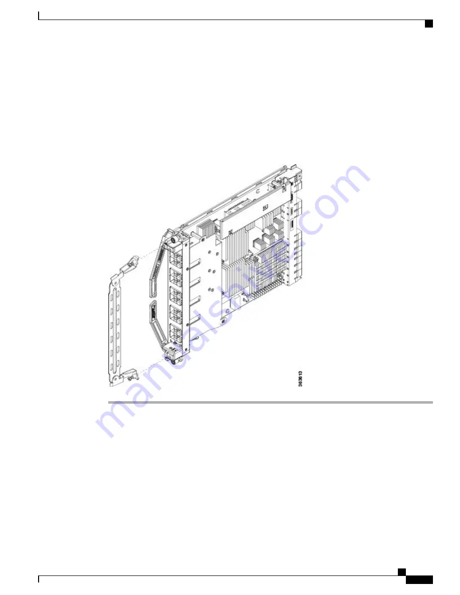
Attach the vertical cable management bracket to the faceplate of the LC using the two screws that came with
it. The dark gray arm should be facing up, and the light gray arm should be facing down. See the following
figure.
Figure 42: Attaching the Vertical Cable Management Bracket
Verifying the Installation of a Line Card
Use the Status LED, located on the faceplate of the LC, to verify the correct installation of the LC:
•
When the card is properly installed and no faults are detected, the status LED turns green.
•
When the status LED is solid yellow, either software initialization is in progress during bootup or a fault
exists on the card.
•
When the status LED is blinking yellow, the card is not fully seated.
Hardware Installation Guide for Cisco NCS 4000 Series
89
Installing Route Processor Cards, Fabric Cards, and Line Cards
Verifying the Installation of a Line Card


