The installation of a Cisco NCS 4009 chassis may require space, power, and cooling modifications to a
facility. Therefore, you should plan the site well in advance of the scheduled delivery of the chassis system.
Note
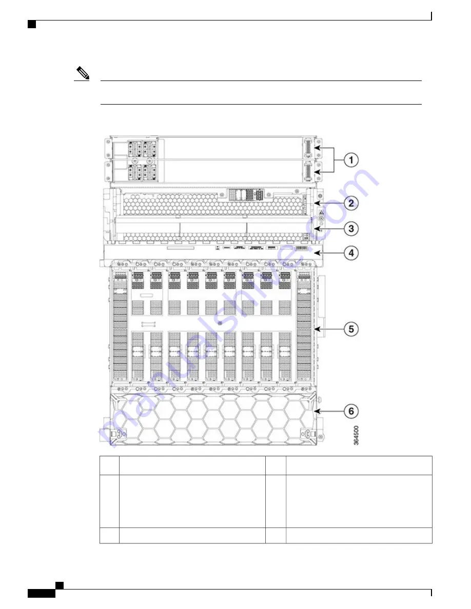
Figure 74: Front View of the Cisco NCS 4009 Chassis
Fiber management
4
Power trays (2)
1
Card cage containing:
•
9 line card slots
•
2 route processor slots
5
External Connection Unit (ECU)/Craft
Panel/Air Outlet
2
4 fabric card slots covered by the inlet air filter
6
Fan tray
3
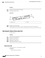
Hardware Installation Guide for Cisco NCS 4000 Series
150
Chassis Overview
About the Cisco NCS 4009 Chassis


