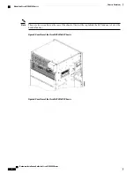
Cards in the top and bottom card cages are not inserted in the same direction. If you consider , the above
figure, as a reference, cards in the bottom card cage are inserted upside down.
Note
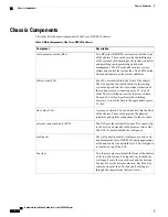
The chassis has the following card slots:
•
Sixteen LC slots:
◦
Eight in the top card cage (LC0 to LC7)
◦
Eight in the bottom card cage (LC8 to LC15)
•
Two RP slots:
◦
One in the top card cage (RP0)
◦
One in the bottom card cage (RP1)
•
Four FC slots:
◦
Two in the top card cage (FC0, FC1)
◦
Two in the bottom card cage (FC2, FC3)
•
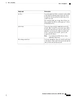
Two fan trays for redundancy at the top and the bottom of the chassis
•
One external connection unit (ECU) located above the top fan tray behind the craft panel
•
Two fiber management areas at the top and the bottom of the chassis
•
One air inlet and two air outlets
•
Eight power modules for redundancy
•
The upper four AC or DC power trays (0-3) are contained within power shelf 0 (PS0) and the lower four
AC or DC power trays (4-7) are contained within power shelf 1 (PS1).
The cards have electrical plugs at the back that plug into electrical connectors on the shelf backplane. When
the ejectors are fully closed, the card plugs into the assembly backplane.
The chassis has eight power modules for redundancy:
•
The upper four power modules are contained within power tray 0 (PS0). They are named as follows:
PS0-PM0, PS0-PM1, PS0-PM2, and PS0-PM3.
•
The lower four power modules are contained within power tray 1 (PS1). They are named as follows:
PS1-PM0, PS1-PM1, PS1-PM2, and PS1-PM3.
Hardware Installation Guide for Cisco NCS 4000 Series
11
Chassis Overview
Chassis Slot Numbers


