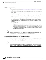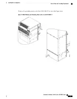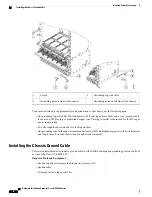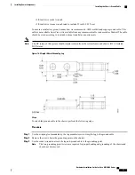
For chassis installation, make sure that enough room exists in front of the chassis to accommodate
installation personnel and the scissor lift (or similar lifting device) used to hold the chassis in the rack
while it is bolted in.
Note
Front and Rear Clearances
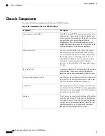
The site requires the following front and rear clearances for chassis installation and maintenance access:
•
To install the chassis in the equipment rack: approximately 40 inches (101.6cm)
•
To service components and allow system airflow (both in front of and behind the chassis): 36 inches
(91.4 cm)
Maintain at least 6 inches (15.2 cm) of clearance at both the inlet and exhaust openings on the chassis and
on the power modules to allow sufficient airflow.
Note
Cable Management
As the size of the routing system increases, the cabling required for the chassis increases. For example, a fully
loaded Cisco NCS 4016 chassis has more cables connected to it than a partially loaded chassis. The cabling
runs must be carefully planned. The basic configurations for various routing systems should be arranged to
minimize the complexity and length of the cable runs. Precut and terminated cables are considered part of the
basic configuration.
•
CONSOLE or AUX RJ-45 RS-232 serial ports on the route processor cards for terminal connections
•
Ethernet ports on the route processor cards for connecting network management equipment
•
Modular service cards (MSCs) and physical layer interface modules (PLIMs) for data connections
The upper and lower cable management trays are for organizing these interface cables to keep the front of the
chassis clear and to eliminate sharp bends in the cables.
Excessive bending can damage interface cables.
Caution
Route Processor Cables
As you consider system cabling, see the table below, to determine the types of cables required to connect to
ports on the route processor (RP).
Hardware Installation Guide for Cisco NCS 4000 Series
20
Site Planning Considerations
Front and Rear Clearances

