DC-Powered Chassis
Use a 6 AWG wire rated 75°C minimum, for DC power modules connection. The system accepts a nominal
input voltage of -48 VDC or -60VDC, with an operational tolerance range of -40.5 to -72 VDC. One dedicated,
commensurately rated DC power source is required for each power module connection. Each power feed shall
be provided with a double pole breaker, rated not more than 60A, with medium delay.
Follow the power and sizing requirements for your site.
Note
The Short Circuit protection Breaker shall not be rated more than 60A.
Note
Power redundancy requirements vary based on the system configuration (number and type of line cards, etc.).
DC-powered systems are N+1 protected.
Power connections to the power tray for each DC power module requires four cables: two source cables and
two return cables.
For DC power cables, we recommend 6 AWG high-strand-count copper wire cables, rated 75°C minimum.
The size of the cables depends on your chassis location from the source power. Follow your local practices
for determining cable size. DC power cables are not available from Cisco, but they are available from any
commercial cable vendor.
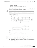
You must terminate DC power cables using cable lugs at the power tray end. The lugs required for the input
power are provided with the power modules.
Hazardous voltage or energy may be present on power terminals. Always replace cover when
terminals are not in service. Be sure uninsulated conductors are not accessible when cover is in
place.
Statement 1086
Warning
Only trained and qualified personnel should be allowed to install, replace, or service this equipment.
Statement 1030
Warning
Before connecting DC power cables to the power system, make sure that the input power cords are not
energized.
Note
Ensure that there is a readily accessible disconnect device incorporated in the building
’
s installation wiring.
Note
Circuit breaker and fuse lockout procedures should follow the rules and regulations in the National Electrical
Code (NEC) and any local codes.
Note
Hardware Installation Guide for Cisco NCS 4000 Series
25
Installing Power Components
Power Connection Guidelines

