• Be careful not to lay any tools on the aluminum honeycomb panel, or insert your fingers into the panel.
Guidelines for Installing and Removing a Card
• Online (in-service) insertion and removal (OIR) is supported, enabling you to remove and install cards
while the chassis is operating. OIR is seamless to users on the network, maintains all routing information,
and ensures session preservation. You do not need to notify the software or reset the power. You have
the option of using the Cisco IOS XR
shutdown
command before removing a card.
OIR removes power to a specific slot before the card is replaced. The power remains on for all other card
slots.
Note
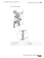
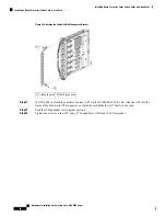
• The different cards in the chassis are all attached to the chassis itself using a pair of ejector levers and
captive screws. The two ejector levers release the card from its backplane connector. The exact locations
of the ejector levers and captive screws can vary slightly from card to card, but they are generally in the
same locations: on the upper and bottom ends of the faceplate.
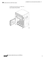
• When you remove a card, press the OIR buttons before using the ejector levers to ensure that the connector
pins disconnect from the backplane in the sequence expected by the chassis.
• The correct card orientation is shown by the eject symbol on the OIR buttons. The symbol must be
oriented upward for cards in NCS 4009, or in the top row for NCS 4016, and downward for cards in the
bottom row in the NCS 4016 chassis.
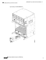
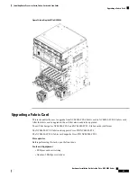
• Every FC, LC, and RP card has a key mounted on the board that matches a corresponding slot on the
chassis side (top of each card slot). This key-slot mechanism prevents a card from being inserted into
the wrong, non-matching card slot. It also prevents a card from being inserted upside down. When a card
is inserted into the wrong card slot or upside down, the key will get blocked against the chassis card
guide and not slide though the slot. When the key gets blocked, remove the card and find the correct card
slot.
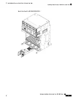
• Any unused card slots that are uncovered would allow air used for chassis cooling to escape. Therefore,
to ensure proper air flow and maintain system EMC and safety compliance, any unused LC slots must
contain filler cards, and all FC and RP cards must remain installed in their card slots.
• Fully insert all FC and RP cards into the chassis before tightening their captive screws.
The chassis may indicate a hardware failure if you do not follow proper procedures. Remove or install only
one card at a time. Allow at least 30 seconds for the chassis to complete its tasks before removing or installing
another card.
Caution
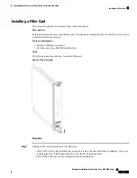
Installing and Removing a Filler Card
To ensure thermal regulation in the chassis, keep filler cards installed in all slots that do not have an LC.
Caution
This section contains the following procedures:
Hardware Installation Guide for the Cisco NCS 4000 Series
30
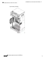
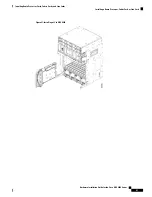
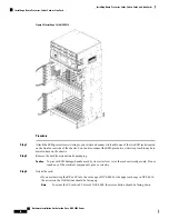
Installing Route Processor Cards, Fabric Cards, and Line Cards
Guidelines for Installing and Removing a Card
Summary of Contents for NCS 4000 Series
Page 2: ......