Procedure
Step 1
Check that the power switch is set to the OFF (0) position. The power switch is on the right of the power tray.
Step 2
Check that the circuit breaker assigned to the AC power source you are connecting is set to off.
Step 3
Verify that the permanent ground connection (central office grounding system) has been installed to the NEBS
grounding location on the chassis.
To ensure that power remains off while you are performing this procedure, lock-out/tag-out the
circuit breaker switch in the OFF (0) position until you are ready to turn it on.
Warning
Step 4
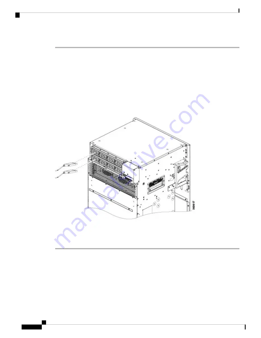
Plug the AC power cord into the receptacle at the rear of the AC power tray.
Step 5
Tighten the screw that clamps the AC power cord plug in place.
Figure 55: Typical AC Power Connections to an AC Power Tray
Step 6
Plug the other end of the AC power cord into the AC source receptacle.
Step 7
Proceed to the
Powering On the Chassis, on page 79
.
Connecting Power to a DC-Powered Chassis
This section contains the procedures to connect the DC source power cables to a DC-powered chassis.
The color coding of source DC power cable leads depends on the color coding of the site DC power source.
Because there is no color code standard for source DC wiring, you must be sure that power source cables are
connected to the power module with the proper positive (+) and negative (–) polarity:
• In some cases, the source DC cable leads might have a positive (+) or a negative (–) label. This is a
relatively safe indication of the polarity,
but you must verify the polarity by measuring the voltage between
Hardware Installation Guide for the Cisco NCS 4000 Series
74
Installing Power Components
Connecting Power to a DC-Powered Chassis
Summary of Contents for NCS 4000 Series
Page 2: ......