•
3/8-inch ratchet wrench with 7/16-pt. socket
•
Voltmeter
Steps
To disconnect the DC input power cables, follow these steps:
Step 1
Attach the ESD-preventive wrist strap to your wrist and connect its leash to one of the two ESD jacks (see
Electrostatic Discharge, on page 11
) on the rear of the FCC. You can also connect the ESD-preventive wrist strap leash
to any bare metal surface on the FCC.
Step 2
Open the input circuit breakers/fuses for the DC cables to be removed and using the voltmeter, verify that there is no
voltage on the cables that are about to be removed.
Step 3
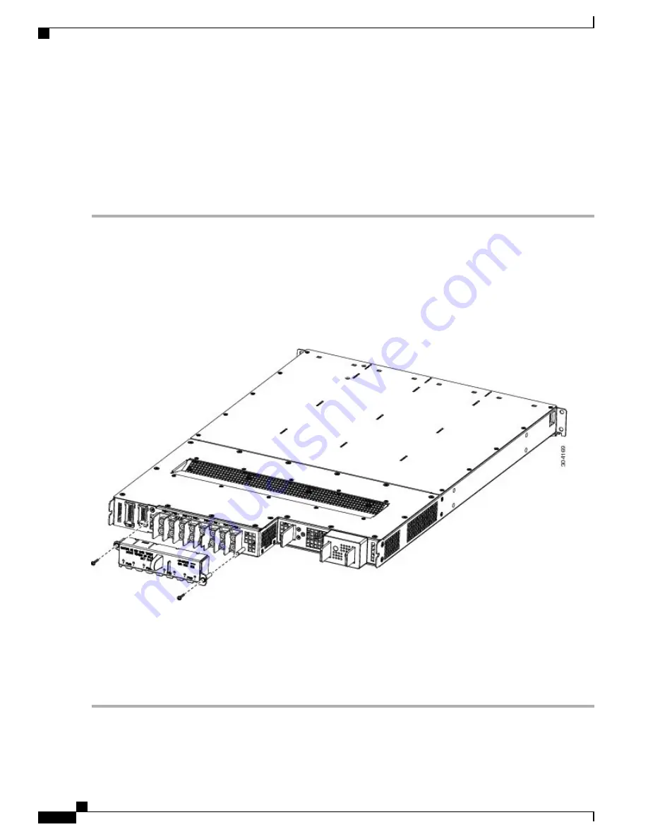
Use the screwdriver to remove the bolts that secure the terminal block cover into the mounting standoff.
Figure 59: DC Terminal Block Cover Installed on Rear of the Power Tray
Step 4
Slide the terminal block cover downwards.
Step 5
Remove the terminal block cover.
Step 6
Using the ratchet wrench, remove the positive and negative cable pairs from each terminal block.
When a cable is removed from the rear of the DC power tray, we recommend that you wrap the cable lug with
standard black electrical tape.
Note
Step 7
Replace the terminal block cover.
Cisco Network Convergence System 6000 Fabric Card Chassis Hardware Installation Guide
98
Removing and Replacing Chassis Components
Removing DC Input Power Cables


