6-29
Cisco Nexus 7000 Series Hardware Installation and Reference Guide
OL-23069-07
Chapter 6 Installing Power Supplies
Connecting a DC Power Supply to DC Power Sources
Note
For all your power connections, if you are using cables with two different colors, use one color
cable for all positive circuits and the other color for all negative circuits.
d.
In each of the uncovered terminal slots, unscrew and remove two nuts (remove a total of eight nuts)
as shown by Callout 3 in
Figure 6-17
.
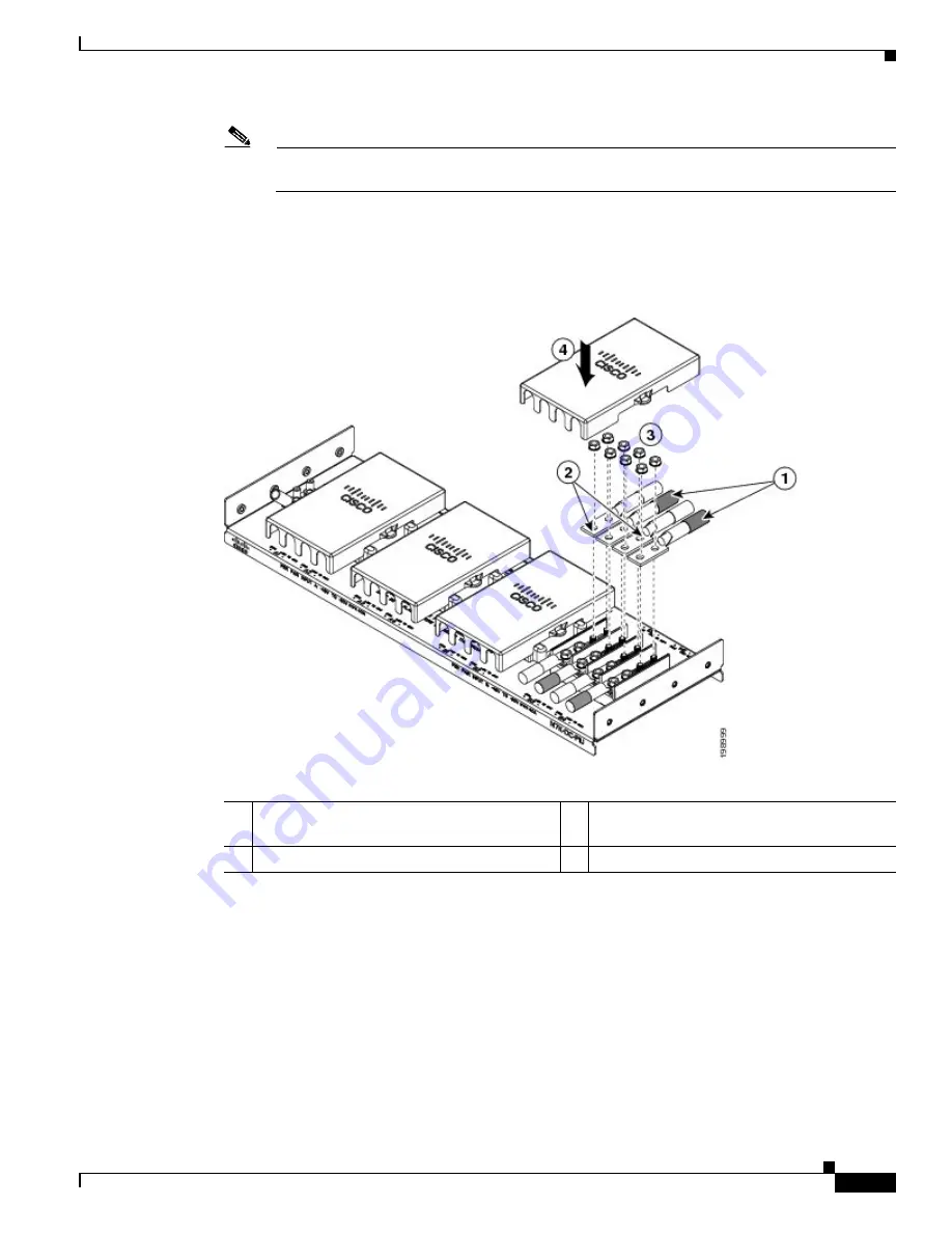
Figure 6-17
Connecting the Negative Inputs to the PIU
e.
Attach the lugs for each of the four power source cables to four terminals. Be sure that each negative
cable is attached to a negative terminal and each positive cable is attached to a positive terminal. See
Callouts 1 and 2 in
Figure 6-17
.
f.
Fasten each lug to its terminal poles with two nuts and tighten to 40 in-lb (4.5 N·m). See Callout 3
in
Figure 6-17
).
g.
Replace the safety cover on the PIU as shown by Callout 4 in
Figure 6-17
.
Step 7
Install the four cables from the PIU to the DC power source as follows:
a.
If the wire is not stripped of its insulation for the last 0.75 inches (19 mm), use wire strippers to
remove that amount of insulation from the end of the wire.
1
Attach the negative lugs to negative posts.
3
Fasten each of the four lugs with two M6 nuts
and tighten to 40 in-lb (4.5 N·m).
2
Attach the positive lugs to positive posts.
4
Replace the cover on top of the connections.
Summary of Contents for Nexus 7004
Page 12: ...Contents xii Cisco Nexus 7000 Series Hardware Installation and Reference Guide OL 23069 07 ...
Page 19: ... xix Cisco Nexus 7000 Series Hardware Installation and Reference Guide OL 23069 07 ...
Page 22: ... xxii Cisco Nexus 7000 Series Hardware Installation and Reference Guide OL 23069 07 ...