


E-12
Cisco Nexus 7000 Series Hardware Installation and Reference Guide
OL-23069-07
Appendix E Repacking the Cisco Nexus 7000 Series Switch for Shipment
Repacking the System Components
Warning
When installing or replacing the unit, the ground connection must always be made first and
disconnected last.
Statement 1046
Step 5
Disconnect the switch from the console and the network as follows:
a.
For each supervisor module, disconnect the cables connected to the console, Com/AUX,
Management, and CMP Management ports.
Note
The CMP feature is available only on Supervisor 1 modules.
b.
Disconnect all of the cables from each of the I/O modules.
Step 6
Disconnect the grounding lug from the front of the chassis as follows:
a.
Unscrew the two M4 screws that hold each ground lug to the chassis. For the location of the
grounding pad on the chassis, see
Figure 3-12 on page 3-22
.
b.
Remove the grounding lug from the chassis and place the two screws in the accessory kit.
Step 7
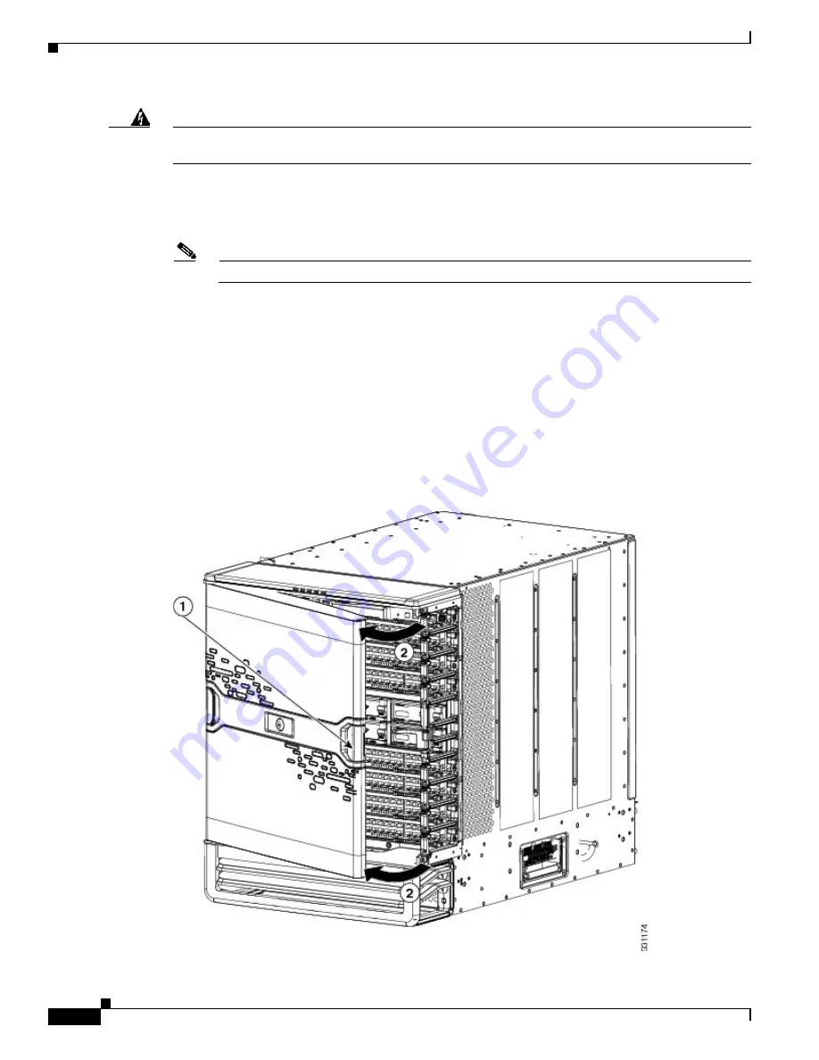
If the chassis includes the optional front door and air-intake frame, remove and repack them as follows:
a.
Open the door by pulling one of its latch handles out until it clicks (the handle clicks when you pull
it out about 30 degrees) and rotate the door away from the chassis (see
Figure E-5
).
Figure E-5
Removing One Side of the Front Door
Summary of Contents for Nexus 7004
Page 12: ...Contents xii Cisco Nexus 7000 Series Hardware Installation and Reference Guide OL 23069 07 ...
Page 19: ... xix Cisco Nexus 7000 Series Hardware Installation and Reference Guide OL 23069 07 ...
Page 22: ... xxii Cisco Nexus 7000 Series Hardware Installation and Reference Guide OL 23069 07 ...


