E-19
Cisco Nexus 7000 Series Hardware Installation and Reference Guide
OL-23069-07
Appendix E Repacking the Cisco Nexus 7000 Series Switch for Shipment
Repacking the System Components
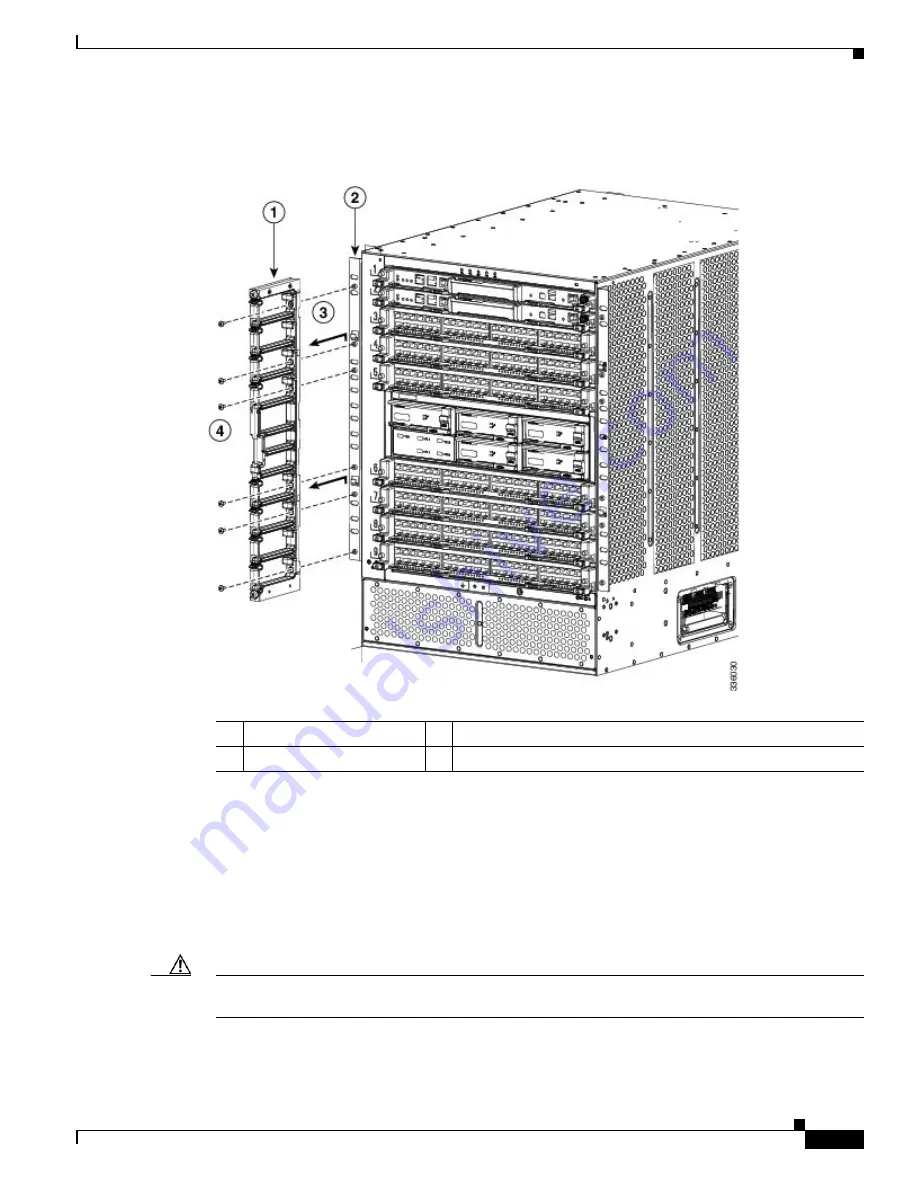
Figure E-12
Removing a Side Cable Management Frame
c.
Remove the other cable management frame by repeating Step 7b.
Step 9
Disconnect the ground cable from the chassis by loosening and removing its two M4 screws. Place the
screws in a small parts bag for the accessory kit. For a location of the grounding pad, see
Figure 3-12 on
page 3-22
.
Step 10
Remove the chassis from the rack by following these steps:
a.
Unscrew 12 screws holding the chassis to each side of the rack (6 screws on each side). Place the
screws in the small parts bag for the accessory kit.
Caution
Do not remove the six screws used to hold the two bottom support brackets to the rack. They are required
to hold the chassis in place until you remove it from the rack.
1
Cable management frame
3
Frame removed by pulling up and then away from the chassis
2
Front-mount bracket
4
Six M4 screws to be removed.
Summary of Contents for Nexus 7004
Page 12: ...Contents xii Cisco Nexus 7000 Series Hardware Installation and Reference Guide OL 23069 07 ...
Page 19: ... xix Cisco Nexus 7000 Series Hardware Installation and Reference Guide OL 23069 07 ...
Page 22: ... xxii Cisco Nexus 7000 Series Hardware Installation and Reference Guide OL 23069 07 ...