


2-10
Cisco Nexus 7000 Series Hardware Installation and Reference Guide
OL-23069-07
Chapter 2 Installing a Cisco Nexus 7004 Chassis
Grounding the Cisco Nexus 7004 Chassis
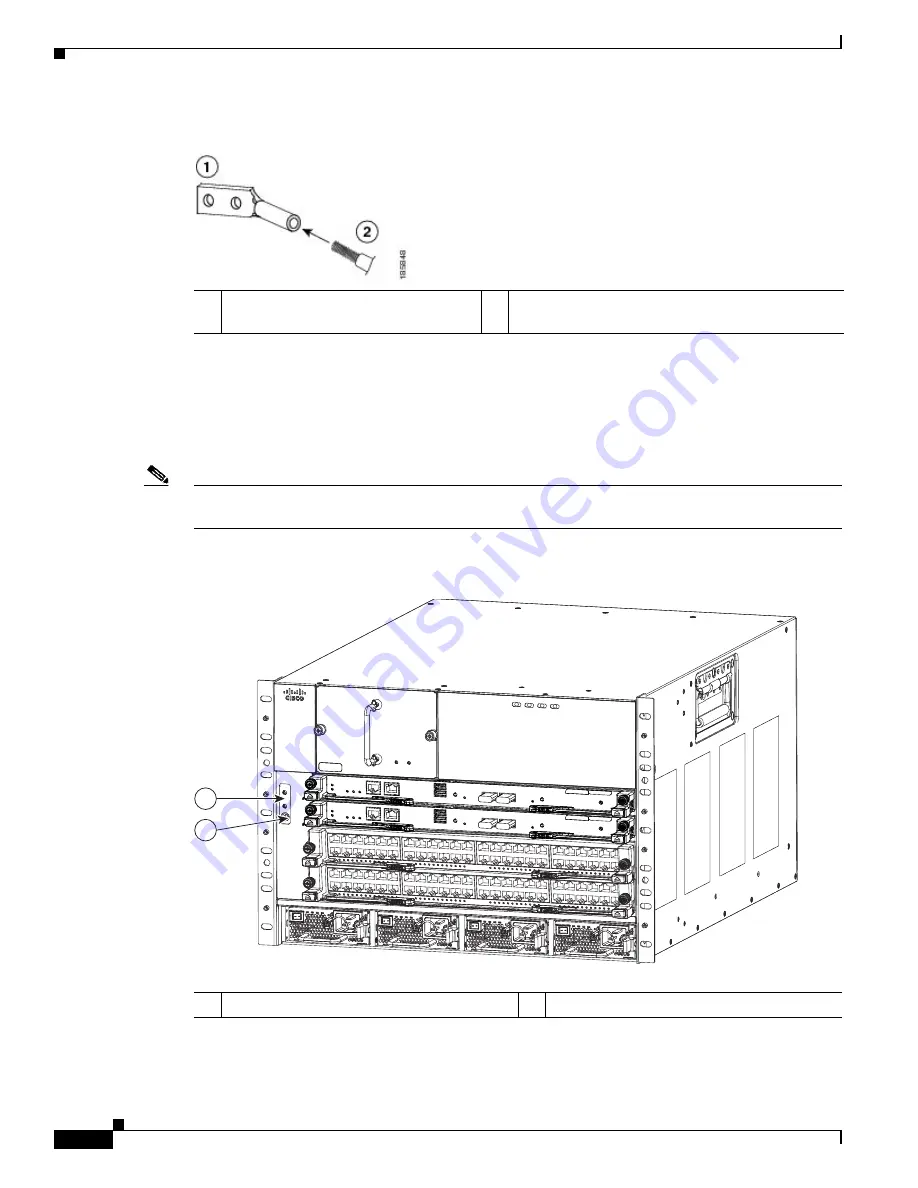
Figure 2-3
Inserting the Grounding Wire in the Grounding Lug
Step 3
Use the crimping tool to crimp the lug to the grounding wire. Verify that the ground wire is securely
attached to the ground lug by attempting to pull the wire out of the crimped lug.
Step 4
Remove the adhesive label from the system grounding pad on the chassis, secure the grounding wire lug
to the grounding pad with two M4 screws, and tighten the screws to 11.5 to 15 in-lb (1.3 to 1.7 N·m).
Callout 1 in
Figure 2-4
shows the location of the grounding pad on the front side of the chassis.
Note
Be sure that the grounding lug and wire do not block the ESD port by positioning the lug and wire
connection above the grounding port.
Figure 2-4
Grounding Pad and ESD Port Locations on the Cisco Nexus 7004 Chassis
1
NRTL listed 45-degree grounding lug
2
Grounding cable with 0.75 in. (19 mm) of insulation
stripped from the end
1
Grounding pad
2
ESD port
334693
1
2
Summary of Contents for Nexus 7004
Page 12: ...Contents xii Cisco Nexus 7000 Series Hardware Installation and Reference Guide OL 23069 07 ...
Page 19: ... xix Cisco Nexus 7000 Series Hardware Installation and Reference Guide OL 23069 07 ...
Page 22: ... xxii Cisco Nexus 7000 Series Hardware Installation and Reference Guide OL 23069 07 ...


