


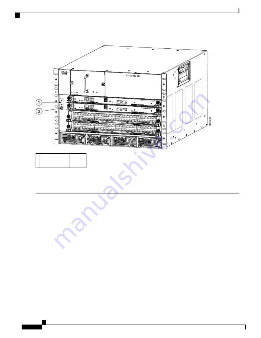
Figure 4: Grounding Pad and ESD Port Locations on the Cisco Nexus 7004 Chassis
ESD
port
2
Grounding
pad
1
Step 5
Prepare the other end of the grounding wire and connect it to an appropriate grounding point in your site to ensure an
adequate earth ground for the switch. If the rack is grounded, connect the grounding wire as explained in the documentation
provided by the vendor for the rack.
Connecting Your ESD Wrist Strap to the Chassis
After you connect the chassis to the data center earth ground, you can ground your ESD wrist strap by plugging
it into the ESD port shown by Callout 2 in
Figure 4: Grounding Pad and ESD Port Locations on the Cisco
Nexus 7004 Chassis, on page 10
.
Installing the Cable Management Frames
After you have fastened the chassis to the rack, you can fasten the cable management frames to the front of
the chassis.
To fasten the cable management frames to the chassis, follow these steps:
SUMMARY STEPS
1.
Align the guide pin on one of the two cable management frames to a guide-pin hole of the same size on
the front-mounting bracket that is already attached to the chassis. The top of the frame should be at the
Installing a Cisco Nexus 7004 Chassis
10
Installing a Cisco Nexus 7004 Chassis
Connecting Your ESD Wrist Strap to the Chassis


