background image

cm] above the installed chassis, use two persons to align the back side of the new chassis to the opening between
the two front posts of the rack and push the chassis into the installed chassis until the chassis mounting brackets
come in contact with the rack mounting rails.

• If you are lifting the chassis manually, use two or more persons to move the back end of the chassis through the

front posts until the chassis mounting brackets come in contact with the mounting rails on the rack, lift the chassis
to the lowest possible RU for it on the rack, and align the screw holes in the chassis mounting brackets to the rack
mounting rails.

Use two persons to lift the chassis by using the handle on each side of the chassis. Do not use the handles on
any of the modules installed on the chassis to lift or move the chassis—these handles are for only removing or
installing the modules.

Caution

Step 3

Use five M6 x 19 mm screws (or 12-24 x 3/4 inch screws) to fasten each side of the chassis to the rack. Tighten each of
the 10 screws to 40 in. lbs (4.5 N.m) (see

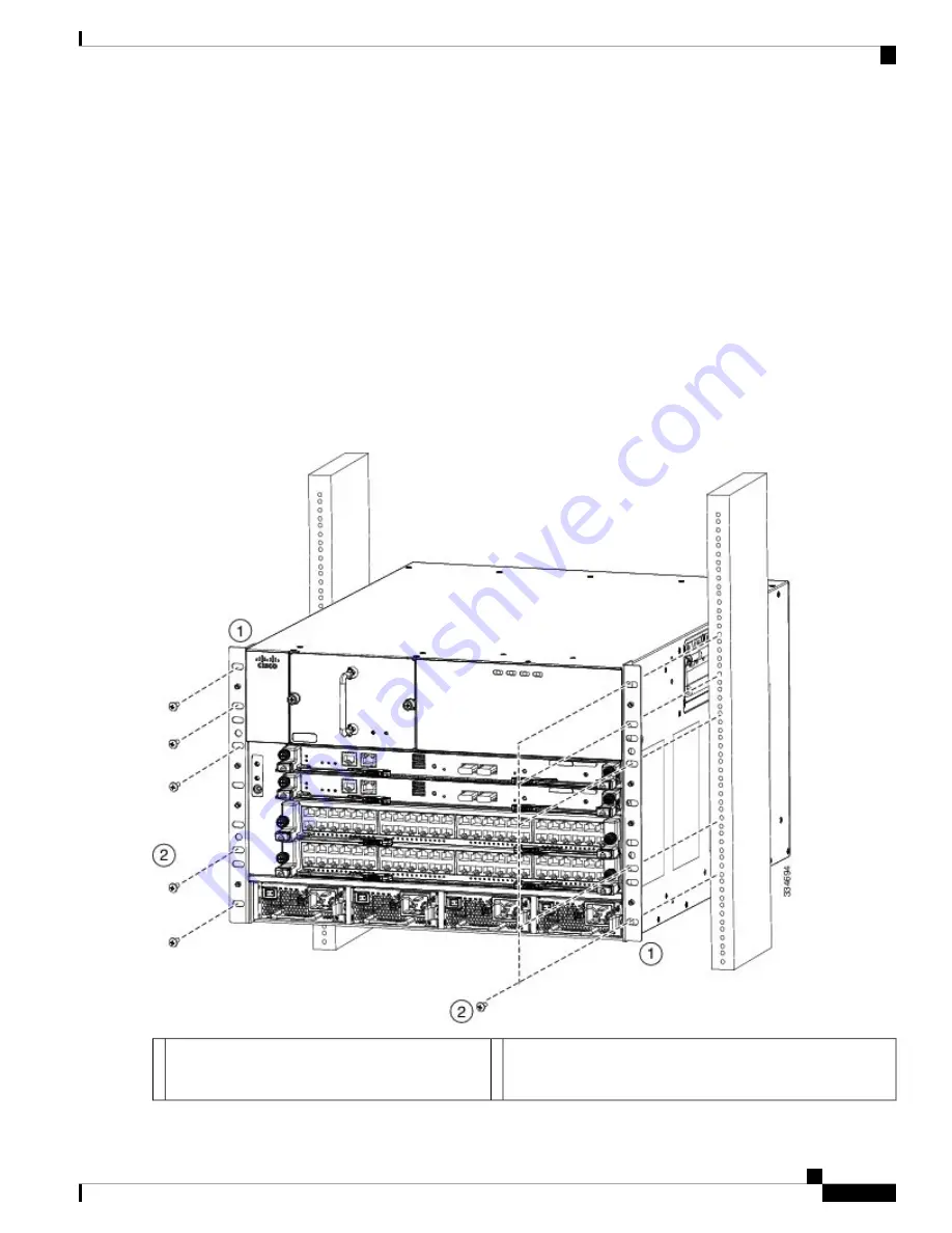
Figure 2: Mounting the Cisco Nexus 7004 Chassis on a Rack, on page 7

).

Figure 2: Mounting the Cisco Nexus 7004 Chassis on a Rack

Five M4 x 6 mm Phillips-head screws used to attach each
front-mount or center-mount bracket to a mounting rail (use a
total of 12 screws for two brackets).

2

Handles used to adjust the chassis placement or to
lift a chassis that weighs less than 120 pounds (54.4
kg).

1

Installing a Cisco Nexus 7004 Chassis

7

Installing a Cisco Nexus 7004 Chassis

Installing the Chassis in a Rack

Summary of Contents for Nexus 7004

Page 1: ...19 inch EIA rack or cabinet before you can install the Cisco Nexus 7004 chassis Make sure that you order the rack or cabinet and have it delivered before installing the chassis Note Required Tools Before you install the Cisco Nexus 7004 chassis into a rack make sure that you have the Cisco Nexus 7004 Accessory Kit see the Cisco Nexus 7004 Switch Accessory Kit section on page C 1 for the contents l...

Page 2: ... mechanism must be in place or the rack must be bolted to the floor before you slide the unit out for servicing Failure to stabilize the rack can cause the rack to tip over Statement 1048 Warning If the rack has bonded construction connect it to the earth ground to enable you to easily ground the system components that you install and to ground your ESD wrist strap This step minimizes the chance o...

Page 3: ...all of the ordered items The shipment should include boxes for the following System chassis which includes the following installed components 2 supervisor modules 1 or 2 I O modules 1 fan tray 2 to 4 power supply units Blank filler plates for any missing supervisor modules I O modules or power supply modules Cisco Nexus 7004 system accessory kit To see a list of what is in the accessory kit see th...

Page 4: ...post 19 inch EIA rack or cabinet that includes such a rack For more information on the rack or cabinet see the Installing a Rack or Cabinet on page 2 Stability hazard The rack stabilizing mechanism must be in place or the rack must be bolted to the floor before you slide the unit out for servicing Failure to stabilize the rack can cause the rack to tip over Statement 1048 Warning To prevent bodily...

Page 5: ...Installing Center Mount Brackets on the Chassis on page 5 Figure 1 Installing Center Mount Brackets on the Chassis Six M4 x 6 mm screws for each bracket 2 Center mount bracket left and right versions 1 Step 2 Use a Phillips head screw driver to secure the bracket to the chassis with the six M4 x 6 mm screws Tighten each screw to 11 5 to 15 in lbs 1 3 to 1 7 N m Step 3 Repeat steps 1 and 2 to insta...

Page 6: ...es or module handles Caution To move the chassis with a mechanical lift position the lift at the elevation of the chassis on its shipping pallet or no more than 0 25 inches 0 64 cm below the level of the pallet and use two persons to push the chassis fully onto the lift To move the chassis manually remove the power supplies as explained in one of the following sections and then use two persons to ...

Page 7: ...using the handle on each side of the chassis Do not use the handles on any of the modules installed on the chassis to lift or move the chassis these handles are for only removing or installing the modules Caution Step 3 Use five M6 x 19 mm screws or 12 24 x 3 4 inch screws to fasten each side of the chassis to the rack Tighten each of the 10 screws to 40 in lbs 4 5 N m see Figure 2 Mounting the Ci...

Page 8: ...e modules This grounding system is active even when the AC power cables are not connected to the system Note You connect the AC power supplies to the earth ground automatically when you connect an AC power supply to an AC power source You connect the DC power supplies to the earth ground before connecting the power supplies to the DC power source see the Connecting a DC Power Supply Directly to DC...

Page 9: ...th 0 75 in 19 mm of insulation stripped from the end 2 NRTL listed 45 degree grounding lug 1 Step 3 Use the crimping tool to crimp the lug to the grounding wire Verify that the ground wire is securely attached to the ground lug by attempting to pull the wire out of the crimped lug Step 4 Remove the adhesive label from the system grounding pad on the chassis secure the grounding wire lug to the gro...

Page 10: ... strap by plugging it into the ESD port shown by Callout 2 in Figure 4 Grounding Pad and ESD Port Locations on the Cisco Nexus 7004 Chassis on page 10 Installing the Cable Management Frames After you have fastened the chassis to the rack you can fasten the cable management frames to the front of the chassis To fasten the cable management frames to the chassis follow these steps SUMMARY STEPS 1 Ali...

Page 11: ...should be at the same level as the top of the chassis see Figure 5 Installing the Cable Management Frames on a Cisco Nexus 7004 Chassis on page 11 Figure 5 Installing the Cable Management Frames on a Cisco Nexus 7004 Chassis Three M3 x 10 mm screws used to fasten the frame to the chassis total of six screws for two frames 2 Guide pins on the cable management frame aligned to two holes in the front...

Page 12: ...SB drive into the expansion flash reader the message will end with slot0 online If you see an offline message or do not see a message either the USB drive is not fully inserted or it is improperly formatted Make sure that the USB drive is fully inserted inside the reader If it is fully inserted either format the card see the Cisco Nexus 7000 Series NX OS Fundamentals Configuration Guide or replace...

Reviews: