


S e n d d o c u m e n t c o m m e n t s t o n e x u s 7 k - d o c f e e d b a c k @ c i s c o . c o m
5-19
Cisco Nexus 7000 Series Hardware Installation and Reference Guide
OL-23069-06
Chapter 5 Installing Power Supply Units
Connecting a DC Power Supply Unit to DC Power Sources
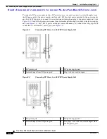
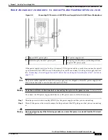
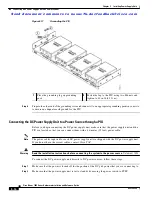
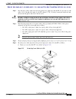
Figure 5-13
Connecting the Negative Inputs to the PIU
b.
Attach two positive input lugs to the positive posts on the rear side of the PIU (see callout 2 in
c.
Fasten all four lugs to the PIU using M6 nuts and tighten each to 40 in-lb (4.5 N·m) (see callout 3
in
).
d.
Place the cover over the connections and snap it into place (see callout 4 in
Step 10
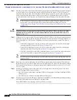
Turn on the power for the power source.
Step 11
Turn the power switch on the DC power supply unit from STBY to ON. The LEDs should flash and the
input LEDS should turn on as follows:
•
If you are outputting 3 kW of power, either Input 1 and Input 2 LEDs will turn green or the Input 3
and Input 4 LEDs will turn green.
•
If you are outputting 6 kW of power, the Input 1, Input 2, Input 3, and Input 4 LEDs will turn green.
If the FAULT LED is lit or blinking, call Cisco TAC for assistance.
1
Attach the negative lugs to negative posts.
3
Fasten each of the four lugs with two M6 nuts
and tighten to 40 in-lb (4.5 N·m).
2
Attach the positive lugs to positive posts.
4
Replace the cover on top of the connections.


