


S e n d d o c u m e n t c o m m e n t s t o n e x u s 7 k - d o c f e e d b a c k @ c i s c o . c o m
9-24
Cisco Nexus 7000 Series Hardware Installation and Reference Guide
OL-23069-06
Chapter 9 Replacement Procedures
Replacing a Supervisor Module
Note
If you stop this procedure at this point without removing the module and need to power it up,
simultaneously press both ejector levers back to the face of the module until they click, secure both of
the module captive screws to the chassis, and then use the
no poweroff module
slot_number
command
to power up the module.
Step 5
Simultaneously rotate the two ejector levers outward to unseat the module from the midplane connector
(see Callout 3 in
Step 6
With a hand on each ejector lever, pull the module part way out of its slot in the chassis.
Step 7
Grasp the front edge of the module with one hand and place your other hand under the lower side of the
module to support its weight. Pull the module out of its slot.
Caution
To prevent ESD damage, avoid touching the electronic circuitry and prevent anything else from coming
in contact with its circuitry.
Step 8
If you are removing the module from a Cisco 7010 chassis, rotate the module 90 degrees
counterclockwise so that it is horizontal and you can see the circuitry from above.
Step 9
For the DIMM in the second memory slot from the front of the supervisor module, rotate the two spring
clips away from the DIMM (see Callout 1 in
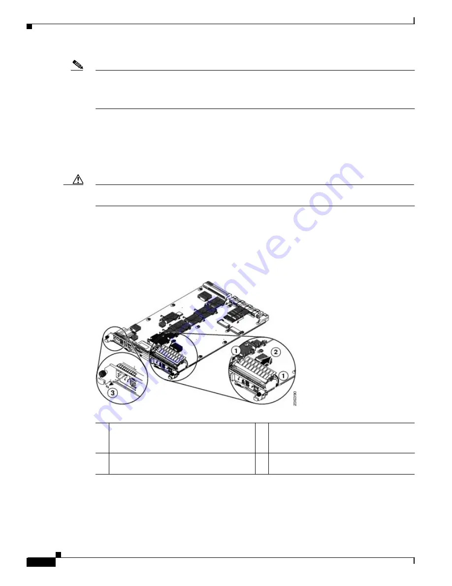
Figure 9-9
Removing a 4-GB DIMM
Step 10
Holding the edges of the 4-GB DIMM with your fingers, slide it out of its memory slot (see Callout 2 in
) and place it in an antistatic bag.
Step 11
Remove the 8-GB label from the front of the module.
Step 12
Rotate both ejector levers away from the front of the supervisor module.
1
On the second socket from the front of the
module, rotate both spring clips away from
the DIMM.
3
Remove the “8 GB” label on the front of the
module.
2
Hold the DIMM by its edges and pull it out of
the memory slot.


