S e n d d o c u m e n t c o m m e n t s t o n e x u s 7 k - d o c f e e d b a c k @ c i s c o . c o m
9-70
Cisco Nexus 7000 Series Hardware Installation and Reference Guide
OL-23069-06
Chapter 9 Replacement Procedures
Replacing the Front Door and Air Intake Assemblies on the Cisco Nexus 7018 Chassis
To replace the front door and air intake assemblies, see the
“Installing a Front Door and Air Intake
Assemblies” section on page 9-70
Installing a Front Door and Air Intake Assemblies
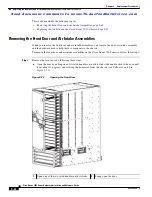
When you install a front door and air intake assembly components, you install hardware to hold the door
and air intake assemblies, attach the door, and then attach the air intake assembly.
To install the front door and air intake assembly components, follow these steps:
Step 1
Open the Front Door and Air Intake kit (69-1962-01) and verify that it includes the following
components:
•
1 front door (800-31268-01)
•
1 air intake frame (800-31270-01)
•
1 bottom hinge bracket (700-28491-02)
•
1 left door stopper (has an L on its base) (700-27454-01)
•
1 right door stopper (has an R on its base) (700-27592-01)
•
8 M4x8 pan head screws (48-0398-01)
•
4 M3x14 pan head screws (48-1699-01)
•
4 ball-point studs (51-5171-01)
Step 2
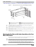
Position the left door stopper (has an L on its base) on the middle of the left side of the cable management
frame and fasten it with two M3x14 pan-head screws as shown in
. Tighten these two screws
to 8.4 to 11 in-lb (0.9 to 1.2 N·m).
1
Box for the kit
6
Small parts bag placed in a filler box
2
Front door box
7
Fold the short flaps on top.
3
Air intake frame box
8
Fold the long flaps on top of the short flaps.
4
Bottom hinge bracket box
9
Tape the long flaps to the box.
5
Filler boxes


