background image

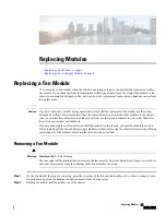
Do not touch the electrical connectors on the back side of the module and prevent anything else from coming
into contact with and damaging the connectors.

Caution

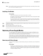
Installing a Fan Module

Before you begin

• A fan slot must be open and ready for the new fan module to be installed.

• You must have a new fan module on hand and ready to install within one minute of removing the original

fan module if the switch is operating.

• The new fan module must have the same airflow direction as the other fan and power supply modules

installed in the switch. All of these modules must have either burgundy coloring (port-side intake airflow)
or they must all have blue coloring (port-side exhaust airflow).

Step 1

Holding the fan module by its handle, align the back of the fan module (the side with the electrical connectors) to the
open fan slot in the chassis.

Step 2

Slide the fan module into the slot until it clicks in place.

Step 3

Verify that the Status (STS) LED turns on and becomes green.

Replacing a Power Supply Module

The switch requires two power supplies for redundancy. With one power supply providing the necessary
power for operations, you can replace the other power supply during operations so long as the new power
supply has the same airflow direction as the other modules in the chassis.

You can replace a power supply with another supported power supply that has the same power source type
and the same wattage rating as the other installed power supply. Additionally, the airflow direction of the
power supply must match or conform to the airflow direction of the installed fan modules. For the airflow
direction used by the switch, see the coloring of the fan modules.

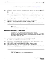
Removing an AC Power Supply

To remove an AC power supply, you must first disconnect the power cable and then remove the module from
the chassis.

Before you begin

• To replace a power supply during operations, you must have a functioning power supply providing power

to the switch while you replace the other power supply. If there is only one power supply installed in the
switch and you need to replace it, install the new power supply in the open slot and power it up before
removing the original power supply.

Replacing Modules

2

Replacing Modules

Installing a Fan Module

Summary of Contents for Nexus 93108TC-EX

Page 1: ... in air from a cold aisle and exhausts to a hot aisle Otherwise the switch can overheat and shutdown If you are changing the airflow direction of all the modules in the chassis you must shutdown the switch before replacing all the fan and power supply modules with modules using the other airflow direction During operations all of the modules must have the same direction of airflow Caution Removing...

Page 2: ...requires two power supplies for redundancy With one power supply providing the necessary power for operations you can replace the other power supply during operations so long as the new power supply has the same airflow direction as the other modules in the chassis You can replace a power supply with another supported power supply that has the same power source type and the same wattage rating as ...

Page 3: ...ly Removing an HVAC HVDC Power Supply You can remove one power supply while the other one provides power to the switch To disconnect the power supply from its power cables you must shut off the power from the power source and then either disconnect a connector for the power cables or release each of three cables from the power supply requires a standard screw driver Step 1 Turn off the circuit bre...

Page 4: ...the power supply handle while pressing the release latch towards the power supply handle Step 4 Pull the power supply out of the bay What to do next You are ready to install a DC power supply in the open slot Installing an AC Power Supply You can replace one power supply while the other one provides power to the switch Before you begin The power supply that you are installing must be capable of us...

Page 5: ... until it clicks in place Step 3 Attach the power cable to the electrical outlet on the front of the power supply Step 4 Make sure that the other end of the power cable is attached to the appropriate power source for the power supply Depending on the outlet receptacle on your power distribution unit you might need the optional jumper cable to connect the switch to your outlet receptacle Note Step ...

Page 6: ...lectrical connector block insert the block into the power receptacle on the power supply If the electrical cables have not been connected to the electrical connector block wire them as described in Wiring a 48 V DC Electrical Connector Block on page 7 Step 4 Make sure that the other end of the power cable is connected to the appropriate power source for the power supply Step 5 If using a DC power ...

Page 7: ...block insert the block into the power receptacle on the power supply If the electrical cables have not been connected to the electrical connector block wire them as described in Wiring a 48 V DC Electrical Connector Block on page 7 Step 3 Turn on the circuit breaker for the DC power source connected to the power supply Step 4 Verify that the power supply is operational by making sure that the powe...

Page 8: ...turn DC cable 3 Step 5 Use a small screwdriver to depress the spring loaded wire retainer lever on the lower spring cage wire connector Insert your green ground wire into the aperture and then release the lever Step 6 Use a small screwdriver to depress the spring loaded wire retainer lever on the middle spring cage wire connector Insert your black DC negative wire into the aperture and then releas...

Reviews: