background image

Installing the Chassis

Installation Options with Rack-Mount Kits, Racks, and Cabinets, on page 1

Install a Rack, on page 2

Unpacking and Inspecting a New Switch, on page 2

Planning How to Position the Chassis in the Rack, on page 3

Installing the Chassis in a Two-Post Rack, on page 4

Installing the Chassis in a Four-Post Rack, on page 8

Grounding the Chassis, on page 13

Powering Up the Switch, on page 15

Installation Options with Rack-Mount Kits, Racks, and Cabinets

The rack-mount kit enables you to install the switch into racks of varying depths. You can position the switch
with easy access to either the port connections or the fan and power supply modules.

You can install the switch using the following rack-mount options:

• Rack-mount kit (N9K-C9300-RMK) which you can order from Cisco.

You can install the switch in the following types of racks:

• Open EIA rack

• Perforated EIA cabinet

The rack or cabinet that you use must meet the requirements listed the in

General Requirements for Cabinets

and Racks

section.

You are responsible for verifying that your rack and rack-mount hardware comply with the guidelines that
are described in this doc.

Note

Installing the Chassis

1

Summary of Contents for Nexus 93128TX

Page 1: ...les you to install the switch into racks of varying depths You can position the switch with easy access to either the port connections or the fan and power supply modules You can install the switch using the following rack mount options Rack mount kit N9K C9300 RMK which you can order from Cisco You can install the switch in the following types of racks Open EIA rack Perforated EIA cabinet The rac...

Page 2: ...lectric shock and fire take care when connecting units to the supply circuit so that wiring is not overloaded Warning If you are not using power redundancy or are using n 1 redundancy you need only one power source If you are using n n redundancy you need two power sources Note Unpacking and Inspecting a New Switch Before you install a new chassis you need to unpack and inspect it to be sure that ...

Page 3: ... Port side exhaust airflow with blue coloring N9K C9300 FAN2 B Port side intake airflow with burgundy coloring N9K C9300 FAN2 Switch accessory kit Rack mount kit Step 2 Check the contents of the box for damage Step 3 If you notice any discrepancies or damage send the following information to your customer service representative by email Invoice number of the shipper see the packing slip Model and ...

Page 4: ...t by the fan modules You can plan the positioning of the switch so that its ports are located close to ports on connected devices or so that the fan and power supply modules are conveniently located in a maintenance aisle and then order the modules that move coolant air in the appropriate direction from the cold aisle to the hot aisle All fan and power supply modules in the same switch must operat...

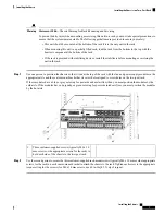
Page 5: ...t have the following tools and equipment Manual Phillips head torque screwdriver Center mount bracket kit Step 1 Align one of the two center mount brackets on the left or right side of the chassis and be sure that the angled portion is facing the front of the chassis see the following figure Be sure to align four of the screw holes on the larger side of the bracket with the four screw holes near t...

Page 6: ...ring use the same direction of airflow as used by the fan modules Note Statement 1074 Comply with Local and National Electrical Codes To reduce risk of electric shock or fire installation of the equipment must comply with local and national electrical codes Warning Statement 1032 Lifting the Chassis To prevent personal injury or damage to the chassis never attempt to lift or tilt the chassis using...

Page 7: ...odules in the appropriate aisle and the center mount bracket has its screw holes aligned to screw holes on the two post rack If these modules have a blue or gray coloring for port side exhaust airflow then you must position the modules by the cold aisle If the modules have a burgundy or green coloring for port side intake airflow you must position the modules by the hot aisle Three customer suppli...

Page 8: ... burgundy coloring for fan modules airflow requires that the bottom support rail with the chassis stop be located on the hot aisle side of the rack Port side exhaust blue coloring for fan modules airflow requires that the bottom support rail with the chassis stop be located on the cold aisle side of the rack Statement 1074 Comply with Local and National Electrical Codes To reduce risk of electric ...

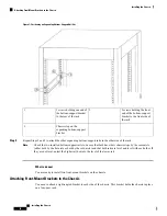
Page 9: ...es have burgundy port side intake modules you must position the bottom support rails so that the chassis stop is positioned by the hot aisle Step 2 Separate the two sliders that make up one bottom support rail and position the half with the chassis stop by the appropriate aisle for the fan and power supply modules Also make sure that there is at least 1 rack unit open above the bottom support rail...

Page 10: ... support rails to be sure that both have their chassis stops by the same aisle either both by the hot aisle or both by the cold aisle and that both rails are level and level with each other If they are not level adjust the higher rail down to the level of the lower rail Note What to do next You are ready to install two front mount brackets on the chassis Attaching Front Mount Brackets to the Chass...

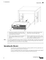
Page 11: ... 6 mm screws to attach the bracket to the chassis Tighten each screw to 11 to 15 in lb 1 2 to 1 7 N m Step 3 Repeat Steps 1 and 2 to attach the second center mount bracket to the other side of the chassis What to do next You are ready to mount the chassis to the four post rack Installing the Chassis in a Four Post Rack You need to slide the chassis onto the bottom support rails so that the power s...

Page 12: ...ent bodily injury when mounting or servicing this unit in a rack you must take special precautions to ensure that the system remains stable The following guidelines are provided to ensure your safety This unit should be mounted at the bottom of the rack if it is the only unit in the rack When mounting this unit in a partially filled rack load the rack from the bottom to the top with the heaviest c...

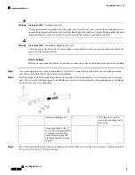
Page 13: ...ied rack mount screw an M6 x 10 mm screw or other appropriate screw for the rack to attach each of the two mounting brackets on the chassis to the rack and tighten each screw to the appropriate torque setting for the screw for M6 x 10 mm screws use 40 in lbs 4 5 N m of torque Grounding the Chassis The switch chassis is automatically grounded when you properly install the switch in a grounded rack ...

Page 14: ... tool to remove approximately 0 75 inch 19 mm of the covering from the end of the grounding wire We recommend 6 AWG wire for the U S installations Step 2 Insert the stripped end of the grounding wire into the open end of the grounding lug Use a crimping tool to crimp the lug to the wire see the following figure Verify that the ground wire is securely attached to the grounding lug by attempting to ...

Page 15: ...tallation Instructions Read the installation instructions before using installing or connecting the system to the power source Warning Statement 1018 Supply Circuit To reduce risk of electric shock and fire take care when connecting units to the supply circuit so that wiring is not overloaded Warning Before you begin Switch installed in a rack and connected to an earth ground Recommended power cab...

Page 16: ...er supply Make sure that your red DC positive wire aligns with the power supply label DC If you require n n redundancy be sure that each power supply is powered by a different power source Note Connecting an HVAC HVDC power supply 1 Using the recommended power cable for your country or region see Power Cable Specifications insert the Saf D Grid connector on the power cable to the power receptacle ...

Page 17: ...ccidentally touching the terminals when the power is on 4 Turn the power on at the circuit breaker 3 Verify that the LED is on and green If the LED is off check the AC power source circuit breaker to be sure that it is turned on Installing the Chassis 17 Installing the Chassis Powering Up the Switch ...

Page 18: ...Installing the Chassis 18 Installing the Chassis Powering Up the Switch ...

Reviews: