Step 3
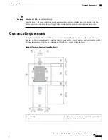
Secure the grounding lug to the chassis grounding pad with two M4 screws (see Callouts 1 and 3 in the previous figure),
and tighten the screws to 12 in-lb (1.36 N·m) of torque.
Step 4
Prepare the other end of the grounding wire and connect it to an appropriate grounding point in your site to ensure an
adequate earth ground for the switch. If the rack is fully bonded and grounded, connect the grounding wire as explained
in the documentation provided by the vendor for the rack.
Connecting the Switch to an AC Power Source
You turn on the switch as soon as you connect its AC power supplies to one or two AC power sources.
Statement 1004
—
Installation Instructions
Read the installation instructions before connecting the system to the power source.
Warning
Statement 1018
—
Supply Circuit
Take care when connecting units to the supply circuit so that wiring is not overloaded.
Warning
Before You Begin
Before you can turn on the switch, you must ensure the following:
•
The switch has enough power supplies to output the power required for all of the modules installed in
the switch. Depending on the power mode that you use for the switch, you need to consider the following:
◦
For combined power mode (no power redundancy), there must be enough power supplies to power
all of the modules in the chassis (no extra power supplies are needed for redundancy). A maximum
of two power supplies are needed.
◦
For power supply redundancy (
n
+1) mode, there must be enough power supplies to power all of
the modules in the chassis and there must be one extra power supply to provide redundancy if one
power supply goes down or is replaced. The maximum number of power supplies needed is the
number used for combined power mode plus one (
n
+1) for redundancy.
◦
For input-source redundancy (
n
+
n
) mode, there must be two equal sets of power supplies, each of
which can power all of the modules in the chassis and is connected to a separate power source. If
one power source goes down, the power supplies connected to the other power source can power
the switch. The maximum number of power supplies is the number of power supplies required for
combined power plus the same number of power supplies (
n
+
n
) for redundancy.
•
The power supplies are installed in the appropriate chassis slots as follows:
◦
For combined power mode or power-supply redundancy mode, the power supplies can be installed
in any power supply slot in the chassis.
◦
For input-source redundancy mode, the power supplies must be divided into two equal sets and
installed as follows:
Cisco Nexus 9504 NX-OS Mode Switch Hardware Installation Guide
24
Installing a Chassis
Connecting the Switch to an AC Power Source


