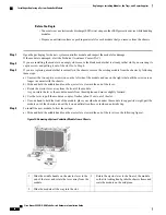
b) Hold the front of the module with one hand and place your other hand under the module to support it.
c) Align the back of the module to the guides in the open controller slot and slide the module all the way into the slot.
The module stops when its front is about 0.25 inches (0.6 cm) outside the front of the chassis.
d) Rotate the ejector lever all the way to the front of the chassis until it locks in place with a click.
The module is fully seated on the midplane.
e) Screw in the two captive screws to secure the module to the chassis. Tighten each of these screws to 8 in-lb (0.9 N·m)
of torque.
f) Verify that the Status (STS) LED turns on and becomes green.
Installing or Replacing an I/O Module
The switch can operate with one or more I/O modules installed in the chassis. If there is at least one I/O module
installed and operating in the chassis, you can replace another I/O module or install a new I/O module in an
empty I/O module slot.
Statement 1029
—
Blank Faceplates and Cover Panels
Blank faceplates and cover panels serve three important functions: they prevent exposure to hazardous
voltages and currents inside the chassis; they contain electromagnetic interference (EMI) that might disrupt
other equipment; and they direct the flow of cooling air through the chassis. Do not operate the system
unless all cards, faceplates, front covers, and rear covers are in place.
Warning
Statement 1034
—
Backplane Voltage
Hazardous voltage or energy is present on the backplane when the system is operating. Use caution when
servicing
Warning
Statement 1051
—
Laser Radiation
Invisible laser radiation may be emitted from disconnected fibers or connectors. Do not stare into beams
or view directly with optical instruments.
Warning
Before You Begin
•
You must wear an electrostatic discharge (ESD) wrist strap or other ESD protective device while handling
modules.
Cisco Nexus 9504 NX-OS Mode Switch Hardware Installation Guide
65
Replacing or Installing Modules, Fan Trays, and Power Supplies
Installing or Replacing an I/O Module


