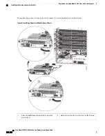
Step 2
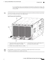
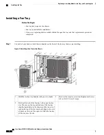
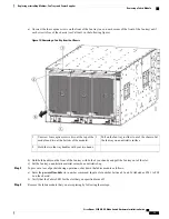
Position the fan tray with its rear (the side with the electrical connectors at the opening for the fan tray slot in the chassis.
Step 3
Align the two tracks on the top of the fan tray with the two sets of rails at the top of the open fan tray slot in the chassis.
Step 4
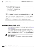
Slide the fan tray all the way into the slot until the front of the fan tray touches the chassis.
Make sure that the four captive screws on the front of the fan tray align with the four screw holes in the chassis.
Step 5
Screw in the four captive screws to secure the fan tray to the chassis. Tighten the screws to 8 in-lb (0.9 N·m) of torque.
Step 6
Verify that the fan tray STATUS LED turns on and becomes green.
Replacing a Fabric Module
The switch uses either three or six fabric modules but you can replace a fabric module while others are
operating. To replace a fabric module, you must do each of the following:
•
Shutdown the fabric module being replaced.
•
Remove the fan tray covering the fabric module in the chassis.
•
Remove the fabric module.
•
Install the new fabric module.
•
Reinstall the fan tray over the fabric module.
•
Activate the fabric module.
To maintain the designed airflow while you remove the fan tray, the fans in the other fan trays increase their
speed. During operations, we recommend that you remove only one fan tray at a time and replace that fan
tray within three minutes to avoid the possibility of having the switch overheat and shut down. If you remove
more than one fan tray at a time, the switch will shut down if you do not replace the extra missing fan trays
within two minutes (the shutdown can occur earlier if an overtemperature condition occurs).
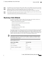
If the switch does not have all of the fabric slots filled, fill them as indicated in the following table and
insert blank filler plates in the open slots. If you do not fill the recommended slots with fabric modules,
some of the fans will not power up.
Note
Table 2: Fabric Module Slots to Fill
Slots to be Filled
Number of Fabric Modules
N.A.
1 (Not allowed)
N.A.
2 (Not recommended)
22, 24, and 26
3 (Minimum recommended number)
22, 23, 24, and 26
4
Cisco Nexus 9504 NX-OS Mode Switch Hardware Installation Guide
71
Replacing or Installing Modules, Fan Trays, and Power Supplies
Replacing a Fabric Module

