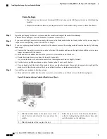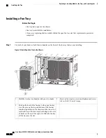
Position the back of the fan tray to the open fan tray
slot. The pins on the top and bottom of the fan tray
should align to holes in the chassis and the two sets
of rails on the top of the fan tray should align to
two sets of tracks on the top of the open slot. Slide
the fan tray all the way into the slot.
2
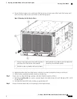
b) Position the fan tray with its rear (the side with the electrical connectors at the opening for the fan tray slot in the
chassis.
c) Align the two tracks on the top of the fan tray with the two sets of rails at the top of the open fan tray slot in the
chassis.
d) Slide the fan tray all the way into the slot until the front of the fan tray touches the chassis.
Make sure that the four captive screws on the front of the fan tray align with the four screw holes in the chassis.
e) Screw in the four captive screws to secure the fan tray to the chassis. Tighten the screws to 8 in-lb (0.9 N·m) of
torque.
f) Verify that the fan tray and fabric module STATUS LEDs (on the fan tray) turn on and become green.
What to Do Next
You are ready to reinstall the fan tray that covers the newly installed fabric module.
Installing a 3-kW AC Power Supply
The number of 3-kW power supplies that you install depends on the power requirements of the switch and
the power mode that you are using. To determine the power requirements of the switch, see the
section.
If you are using only one power source for combined mode or power-supply (
n
+1) redundancy mode, you
can install the power supplies in any of the power supply slots on the chassis. If you are using two power
sources for input-source (grid or
n
+
n
) redundancy mode, you must connect the power supplies in slots 1 and
2 to one power source and the power supplies in slots 3 and 4 to the other power source. With input-source
redundancy mode, divide the power supplies evenly between the first four slots and the last four slots so that
the amount of redundant power for the switch equals the amount of available power for the switch.
Statement 1034
—
Backplane Voltage
Hazardous voltage or energy is present on the backplane when the system is operating. Use caution when
servicing
Warning
Cisco Nexus 9504 NX-OS Mode Switch Hardware Installation Guide
78
Replacing or Installing Modules, Fan Trays, and Power Supplies
Installing a 3-kW AC Power Supply

