Statement 1029
—
Blank Faceplates and Cover Panels
Blank faceplates and cover panels serve three important functions: they prevent exposure to hazardous
voltages and currents inside the chassis; they contain electromagnetic interference (EMI) that might disrupt
other equipment; and they direct the flow of cooling air through the chassis. Do not operate the system
unless all cards, faceplates, front covers, and rear covers are in place.
Warning
Before You Begin
•
The AC power source must be installed within reach of the power cables.
•
The AC power source must meet the power specifications required by the switch.
•
There are one or two AC power sources available. If using input-source (grid or
n
+
n
) redundancy, there
must be two power sources available. Otherwise, only one power source is required.
Step 1
Open the packaging for the new 3-kW AC power supply and inspect the module for damage.
If the module is damaged, contact the Technical Assistance Center (TAC).
Step 2
If you are installing the module in an empty slot, remove the blank filler plate that is already in that slot by unscrewing
its captive screw and pulling it out of the slot. If you are using the combined power mode (no power redundancy) or
power-supply (
n
+1) redundancy, you can use any power supply slot in the chassis. If you are using input-source (grid
or
n
+
n
) redundancy mode, you must be sure that you are inserting the power supply in a slot used for the desired power
supply (the power supplies in slots 1 and 2 must be connected to one power source and the power supplies in slots 3 and
4 must be connected to the other power source). Go to Step 4.
Step 3
If you are replacing a power supply that is currently in the chassis, remove the existing module from the chassis by
following these steps:
a) Disconnect the power cable from the power supply and verify that the output and input LEDs turn off.
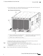
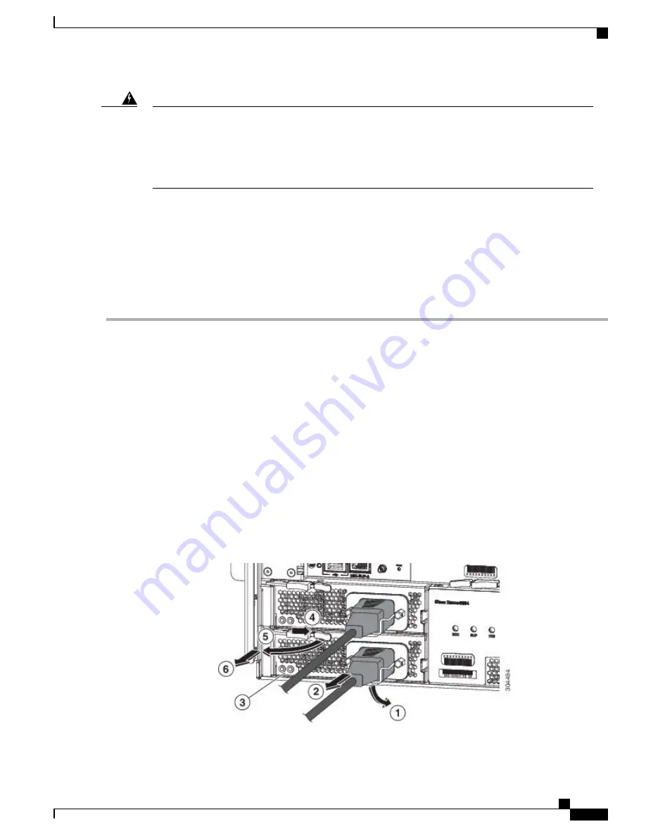
b) Slide the middle of the ejector lever down to the end of the lever and rotate the lever up so that its other end no longer
holds onto the chassis (see the following figure).
The power supply unlocks from the chassis and moves out slightly.
Figure 20: Removing a Power Supply from the Chassis
Cisco Nexus 9504 NX-OS Mode Switch Hardware Installation Guide
79
Replacing or Installing Modules, Fan Trays, and Power Supplies
Installing a 3-kW AC Power Supply

