15-30
Cisco ONS 15454 DWDM Installation and Operations Guide, R6.0
September 2005
Chapter 15 Shelf Hardware Reference
15.8 ONS 15454 ETSI Front Mount Electrical Connection
You can replace the AIP on an in-service system without affecting traffic (except Ethernet traffic on
nodes running a software release earlier than Release 4.0). The circuit repair feature allows you to repair
circuits affected by MAC address changes on one node at a time. Circuit repair works when all nodes are
running the same software version. Each individual AIP upgrade requires an individual circuit repair; if
AIPs are replaced on two nodes, the circuit repair must be performed twice. Always replace an AIP
during a maintenance window.
Caution
Do not use a 2-A AIP with a 5-A fan-tray assembly; doing so causes a blown fuse on the AIP.
Note
Ensure that all nodes in the affected network are running the same software version before replacing the
AIP and repairing circuits. If you need to upgrade nodes to the same software version, no hardware
should be changed or circuit repair performed until after the software upgrade is complete.
15.8 ONS 15454 ETSI Front Mount Electrical Connection
The ONS 15454 ETSI positive and negative power terminals are located on FMEC cards in the Electrical
Facility Connection Assembly (EFCA). The ground connection is the grounding receptacle on the side
panel of the shelf.
The ONS 15454 ETSI EFCA at the top of the shelf has 12 FMEC slots numbered sequentially from left
to right (18 to 29). Slots 18 to 22 and 25 to 29 provide electrical connections. Slots 23 and 24 host the
MIC-A/P and MIC-C/T/P cards, respectively. The MIC-A/P and the MIC-C/T/P cards also connect
alarm, timing, LAN, and craft connections to the ONS 15454 ETSI.
For more information about the MIC-A/P and MIC-C/T/P, see
15.9 ONS 15454 ANSI Alarm Expansion Panel
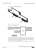
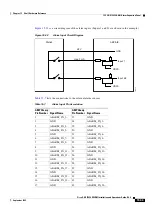
The optional ONS 15454 ANSI alarm expansion panel (AEP) can be used with the Alarm Interface
Controller–International card (AIC-I) card to provide an additional 48 dry alarm contacts for the
ONS 15454 ANSI: 32 inputs and 16 outputs. The AEP is a printed circuit board assembly that is installed
on the backplane.
shows the AEP board; the left connector is the input connector and the
right connector is the output connector.
The AIC-I without an AEP already contains direct alarm contacts. These direct AIC-I alarm contacts are
routed through the backplane to wire-wrap pins accessible from the back of the shelf. If you install an
AEP, you cannot use the alarm contacts on the wire-wrap pins. For more information about the AIC-I,
see
Summary of Contents for ONS 15454 DWDM
Page 38: ...Figures xxxviii Cisco ONS 15454 DWDM Installation and Operations Guide R6 0 August 2005 ...
Page 54: ...Procedures liv Cisco ONS 15454 DWDM Installation and Operations Guide R6 0 August 2005 ...
Page 64: ... 64 Cisco ONS 15454 DWDM Installation and Operations Guide R6 0 August 2005 Chapter ...


