15-45
Cisco ONS 15454 DWDM Installation and Operations Guide, R6.0
September 2005
Chapter 15 Shelf Hardware Reference
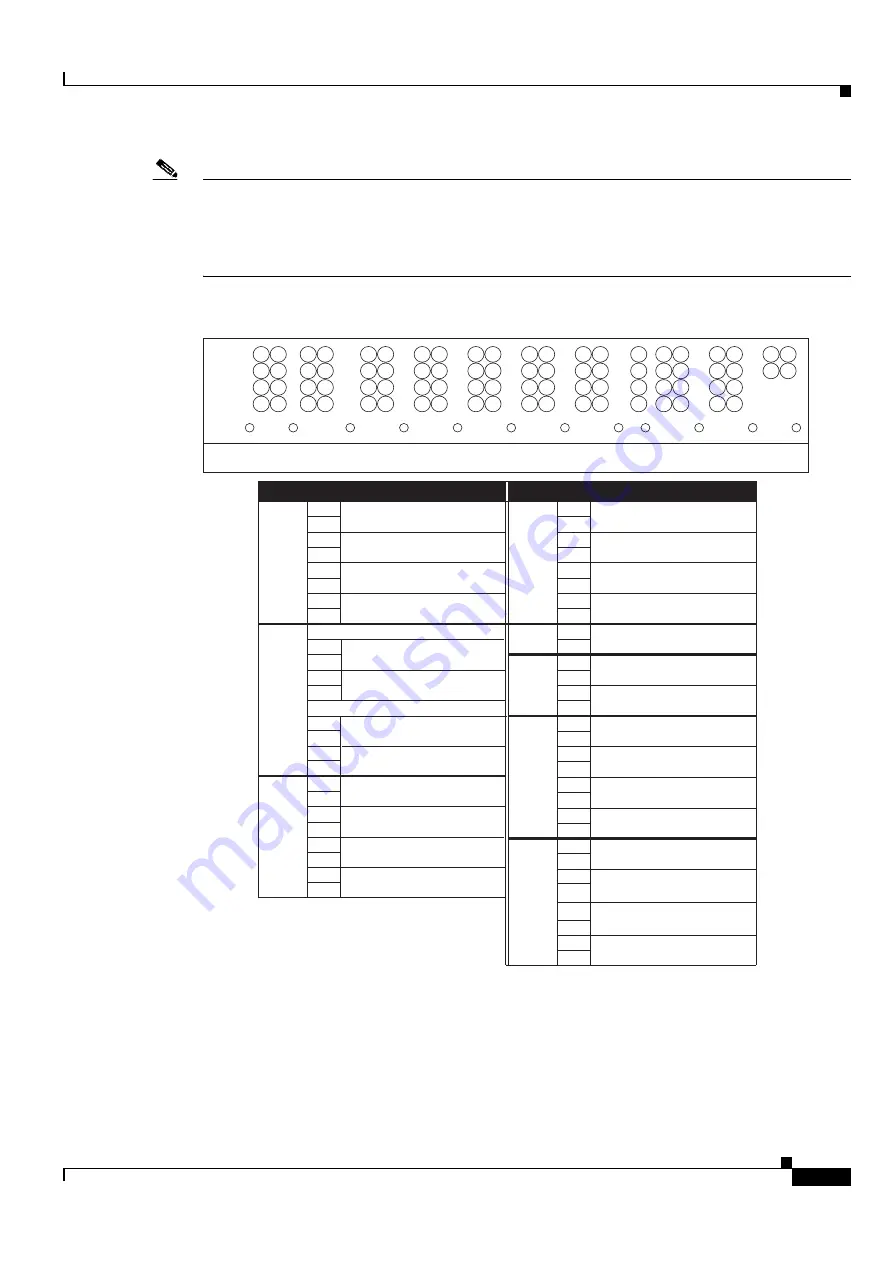
15.14.1 Alarm Contact Connections
Note
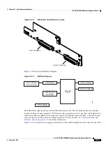
The AIC-I requires a shelf assembly running Software Release 3.4.0 or later. The backplane of the ANSI
shelf contains a wire-wrap field with pin assignment according to the layout in
.
The shelf assembly might be an existing shelf that has been upgraded to R3.4 or later. In this case the
backplane pin labeling appears as indicated in
, but you must use the pin
assignments provided by the AIC-I as shown in
Figure 15-42
ONS 15454 ANSI Backplane Pinouts
15.14.1 Alarm Contact Connections
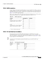
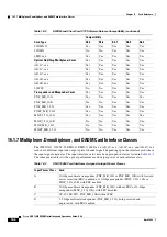
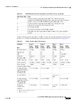
The alarm pin field supports up to 17 alarm contacts, including four audible alarms, four visual alarms,
one alarm cutoff (ACO), and four user-definable alarm input and output contacts.
Field
Pin
Function
Field
Pin
Function
BITS
A1
BITS Output 2 negative (-)
ENVIR
ALARMS
OUT
N/O
A1
Normally open output pair number 1
B1
BITS Output 2 positive (+)
B1
A2
BITS Input 2 negative (-)
A2
Normally open output pair number 2
B2
BITS Input 2 positive (+)
B2
A3
BITS Output 1 negative (-)
A3
Normally open output pair number 3
B3
BITS Output 1 positive (+)
B3
A4
BITS Input 1 negative (-)
A4
Normally open output pair number 4
B4
BITS Input 1 positive (+)
B4
LAN
Connecting to a hub, or switch
ACO
A1
Normally open ACO pair
A1
B1
B1
CRAFT A1
Receive (PC pin #2)
A2
A2
Transmit (PC pin #3)
B2
A3
Ground (PC pin #5)
A4
DTR (PC pin #4)
LOCAL
ALARMS
AUD
(Audible)
N/O
N/O
A1
Alarm output pair number 1: Remote
audible alarm.
B1
B1
ENVIR
ALARMS
IN
A2
Alarm output pair number 2: Critical
audible alarm.
B2
A3
Alarm output pair number 3: Major
audible alarm.
A1
B3
B1
A4
Alarm output pair number 4: Minor
audible alarm.
A2
B4
B2
LOCAL
ALARMS
VIS
(Visual)
A1
Alarm output pair number 1: Remote
visual alarm.
A3
B1
A2
Alarm output pair number 2: Critical
visual alarm.
B2
A3
Alarm output pair number 3: Major
visual alarm.
B3
A4
Alarm output pair number 4: Minor
visual alarm.
B4
A1
A2
B3
A4
B4
RJ-45 pin 2 TX-
RJ-45 pin 1 TX+
RJ-45 pin 2 RX-
RJ-45 pin 1 RX+
RJ-45 pin 6 TX-
Alarm input pair number 1: Reports
closure on connected wires.
Alarm input pair number 2: Reports
closure on connected wires.
Alarm input pair number 3: Reports
closure on connected wires.
Alarm input pair number 4: Reports
closure on connected wires.
Connecting to a PC/Workstation or router
RJ-45 pin 3 TX+
B2
RJ-45 pin 3 RX+
RJ-45 pin 6 RX-
TBOS
AUD
VIS
FG12
FG11
FG10
FG9
FG8
FG7
FG6
FG5
FG4
FG3
FG2
BITS
LAN
FG1
1
1
1
1
1
1
1
1
1
1
1
1
2
2
2
2
2
2
2
2
2
2
3
3
3
3
3
3
3
3
3
3
4
4
4
4
4
4
4
4
4
4
2
3
4
2
A
B
A
B
A
A
B
A
B
A
B
A
B
A
B
A
B
A
B
A
B
LOCAL
ALARMS
CRAFT
MODEM
X . 25
ACO
ENVIR
ALARMS
OUT
IN
38533
Summary of Contents for ONS 15454 DWDM
Page 38: ...Figures xxxviii Cisco ONS 15454 DWDM Installation and Operations Guide R6 0 August 2005 ...
Page 54: ...Procedures liv Cisco ONS 15454 DWDM Installation and Operations Guide R6 0 August 2005 ...
Page 64: ... 64 Cisco ONS 15454 DWDM Installation and Operations Guide R6 0 August 2005 Chapter ...

