16-18
Cisco ONS 15454 DWDM Installation and Operations Guide, R6.0
April 2006
Chapter 16 Card Reference
16.2.4 AIC-I Card
16.2.4.2 External Alarms and Controls
The AIC-I card provides input/output alarm contact closures. You can define up to 12 external alarm
inputs and 4 external alarm inputs/outputs (user configurable). The physical connections are made using
the backplane wire-wrap pins or FMEC connections. See the
“15.9 ONS 15454 ANSI Alarm Expansion
for information about increasing the number of input/output contacts.
LEDs on the front panel of the AIC-I indicate the status of the alarm lines, one LED representing all of
the inputs and one LED representing all of the outputs. External alarms (input contacts) are typically
used for external sensors such as open doors, temperature sensors, flood sensors, and other
environmental conditions. External controls (output contacts) are typically used to drive visual or
audible devices such as bells and lights, but they can control other devices such as generators, heaters,
and fans.
You can program each of the twelve input alarm contacts separately. You can program each of the sixteen
input alarm contacts separately. Choices include:
•
Alarm on Closure or Alarm on Open
•
Alarm severity of any level (Critical, Major, Minor, Not Alarmed, Not Reported)
•
Service Affecting or Non-Service Affecting alarm-service level
•
63-character alarm description for CTC display in the alarm log.
You cannot assign the fan-tray abbreviation for the alarm; the abbreviation reflects the generic name of
the input contacts. The alarm condition remains raised until the external input stops driving the contact
or you provision the alarm input.
The output contacts can be provisioned to close on a trigger or to close manually. The trigger can be a
local alarm severity threshold, a remote alarm severity, or a virtual wire:
•
Local NE alarm severity: A hierarchy of Not Reported, Not Alarmed, Minor, Major, or Critical
alarm severities that you set to cause output closure. For example, if the trigger is set to Minor, a
Minor alarm or above is the trigger.
•
Remote NE alarm severity: Same as the local NE alarm severity but applies to remote alarms only.
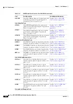
Green/red PWR A LED The PWR A LED is green when a supply voltage within a specified range
has been sensed on supply input A. It is red when the input voltage on supply
input A is out of range.
Green/red PWR B LED
The PWR B LED is green when a supply voltage within a specified range has
been sensed on supply input B. It is red when the input voltage on supply
input B is out of range.
Yellow INPUT LED
The INPUT LED is yellow when there is an alarm condition on at least one
of the alarm inputs.
Yellow OUTPUT LED
The OUTPUT LED is yellow when there is an alarm condition on at least one
of the alarm outputs.
Green RING LED
The RING LED on the local orderwire (LOW) side is flashing green when a
call is received on the LOW.
Green RING LED
The RING LED on the express orderwire (EOW) side is flashing green when
a call is received on the EOW.
Table 16-11
AIC-I Card-Level Indicators (continued)
Card-Level LEDs
Description
Summary of Contents for ONS 15454 DWDM
Page 38: ...Figures xxxviii Cisco ONS 15454 DWDM Installation and Operations Guide R6 0 August 2005 ...
Page 54: ...Procedures liv Cisco ONS 15454 DWDM Installation and Operations Guide R6 0 August 2005 ...
Page 64: ... 64 Cisco ONS 15454 DWDM Installation and Operations Guide R6 0 August 2005 Chapter ...

