16-92
Cisco ONS 15454 DWDM Installation and Operations Guide, R6.0
April 2006
Chapter 16 Card Reference
16.8.3 TXP_MR_2.5G and TXPP_MR_2.5G Cards
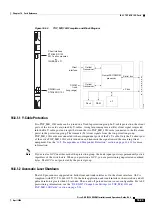
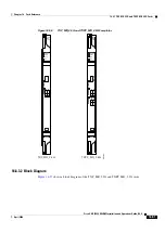
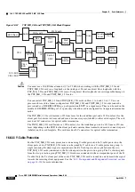
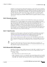
Figure 16-57
TXP_MR_2.5G and TXPP_MR_2.5G Block Diagram
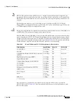
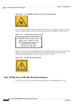
Caution
You must use a 20-dB fiber attenuator (15 to 25 dB) when working with the TXP_MR_2.5G and
TXPP_MR_2.5G cards in a loopback on the trunk port. Do not use direct fiber loopbacks with the
TXP_MR_2.5G and TXPP_MR_2.5G cards. Using direct fiber loopbacks causes irreparable damage to
the TXP_MR_2.5G and TXPP_MR_2.5G cards.
You can install TXP_MR_2.5G and TXPP_MR_2.5G cards in Slots 1 to 6 and 12 to 17. You can
provision this card in a linear configuration. TXP_MR_10G and TXPP_MR_2.5G cards cannot be
provisioned as a BLSR/MS-SPRing, a path protection/SNCP, or a regenerator. They can be used in the
middle of BLSR/MS-SPRing or 1+1 spans only when the card is configured for transparent termination
mode.
The TXP_MR_2.5G card features a 1550-nm laser for the trunk/line port and a 1310-nm laser for the
client port. It contains two transmit and receive connector pairs (labeled) on the card faceplate. The card
uses dual LC connectors for optical cable termination.
The TXPP_MR_2.5G card features a 1550-nm laser for the trunk/line port and a 1310-nm or 850-nm
laser (depending on the SFP) for the client port and contains three transmit and receive connector pairs
(labeled) on the card faceplate. The card uses dual LC connectors for optical cable termination.
16.8.3.3 Y-Cable Protection
For the TXP_MR_2.5G card, protection is done using Y-cable protection. In Y-cable protection, the
client ports of two TXP_MR_2.5G cards can be joined by Y cables in a Y-cable protection group. A
single incoming Rx client signal is injected into the Rx Y-cable port and is split between the two
TXP_MR_2.5G cards (connected to the Rx client ports) in the protection group. The Tx client signals
from the two protection group TXP_MR_2.5G cards are connected to the correspondent ports of the Tx
Y-cable. Only the Tx client port of the active TXP_MR_2.5G card is turned on and transmits the signal
towards the receiving client equipment. See the
“16.9 Transponder and Muxponder Protection” section
for more information.
SFP Client
Switch
Switch
Driver
Tunable
Laser
Switch
Cross
Switch
Limiting
Amp
Limiting
Amp
Main
APD+TA
Protect
APD+TA
Mux
Demux
Mux
Demux
Mux
Demux
CPU
Main
ASIC
Protect
ASIC
FPGA
SCL
FPGA
SCL BUS
2R Tx path
Trunk
Out
2R Rx path
CELL BUS
CPU
I/F
CELL
BUS
DCC
CPU to
GCC
96636
Summary of Contents for ONS 15454 DWDM
Page 38: ...Figures xxxviii Cisco ONS 15454 DWDM Installation and Operations Guide R6 0 August 2005 ...
Page 54: ...Procedures liv Cisco ONS 15454 DWDM Installation and Operations Guide R6 0 August 2005 ...
Page 64: ... 64 Cisco ONS 15454 DWDM Installation and Operations Guide R6 0 August 2005 Chapter ...

