8-32
Cisco ONS 15454 DWDM Installation and Operations Guide, R6.0
September 2005
Chapter 8 Manage Alarms
NTP-G72 Provision External Alarms and Controls on the Alarm Interface Controller-International Card
NTP-G72 Provision External Alarms and Controls on the Alarm
Interface Controller-International Card
Note
On the ONS 15454 ANSI shelf, the AIC-I card alarm provides direct alarm contacts (external alarm
inputs and external control outputs) routed through the backplane to wire-wrap pins accessible from the
back of the shelf. If you install an Alarm Expansion Panel (AEP), the AIC-I alarm contacts cannot be
used. Only the AEP alarm contacts can be used. For further information about the AEP, see
Install the Alarm Expansion Panel (ANSI Only)” procedure on page 1-44
and the
External Wire-Wrap Panel on the AEP (ANSI Only)” procedure on page 1-58
. The ONS 15454 ETSI
shelf is not compatible with the AEP.
Note
For information about the AIC-I alarms, controls, and virtual wire, refer to the
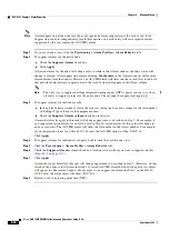
Step 1
If you are using an ONS 15454 ANSI shelf, verify the backplane wiring. If you are using the AEP, see
the
“NTP-G9 Install the Alarm Expansion Panel (ANSI Only)” procedure on page 1-44
. Otherwise, see
the
“NTP-G10 Attach Wires to Alarm, Timing, LAN, and Craft Pin Connections” procedure on
for information about the ONS 15454 backplane pins.
a.
For external alarms, verify that the external device relays are wired to the ENVIR ALARMS IN
backplane pins.
b.
For external controls, verify that the external device relays are wired to the ENVIR ALARMS OUT
backplane pins.
Step 2
If you are using an ONS 15454 ETSI shelf, verify the alarm contact wiring. See the
Wires to Alarm, Timing, LAN, and Craft Pin Connections” procedure on page 1-47
for information
about the ONS 15454 SDH contacts.
a.
For external alarms, verify that the external device relays are wired to the ENVIR ALARMS IN
connector pins.
b.
For external controls, verify the external device relays are wired to the ENVIR ALARMS OUT
connector pins.
Step 3
Complete the
“DLP-G46 Log into CTC” task on page 2-25
. If you are already logged in, continue with
.
Step 4
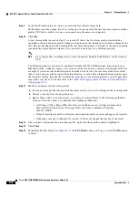
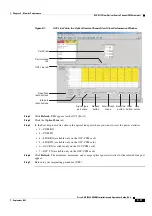
In node view, double-click the AIC-I card on the shelf graphic. The card view appears.
Step 5
Click the
Provisioning > Card
tabs.
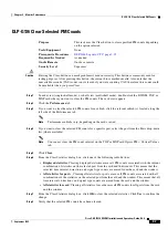
Purpose
Use this procedure to create external (environmental) alarms and external
controls for the AIC-I card.
Tools/Equipment
An AIC-I card must be installed in Slot 9.
Prerequisite Procedures
DLP-G34 Install the AIC-I Card, page 1-75
Required/As Needed
As needed
Onsite/Remote
Onsite or remote
Security Level
Provisioning or higher
Summary of Contents for ONS 15454 DWDM
Page 38: ...Figures xxxviii Cisco ONS 15454 DWDM Installation and Operations Guide R6 0 August 2005 ...
Page 54: ...Procedures liv Cisco ONS 15454 DWDM Installation and Operations Guide R6 0 August 2005 ...
Page 64: ... 64 Cisco ONS 15454 DWDM Installation and Operations Guide R6 0 August 2005 Chapter ...

