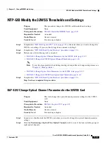
11-34
Cisco ONS 15454 DWDM Installation and Operations Guide, R6.0
September 2005
Chapter 11 Change DWDM Card Settings
DLP-G212 Change Optical Channel Parameters for the 32WSS Card
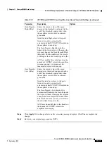
Step 3
Modify any of the settings described in
. The provisionable parameters are listed in the
options column in the table.
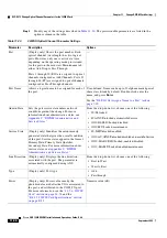
Table 11-20
32WSS Optical Channel Parameter Settings
Parameter
Description
Options
Port
(Display only) Shows the port number. Each
optical channel (wavelength) has two logical
ports. However, only one is active at a time
depending on the operating mode provisioned
for the port on the card view Maintenance tab:
either Add Drop or Pass Through.
Ports 1 through 32 (RX) are assigned to optical
channels configured as Add Channels. Ports 33
through 64 (PT) are assigned to optical channels
configured as Pass-Through channels.
—
Port Name
Allows a logical name to be assigned for each of
the port.
User-defined. Name can be up to 32 alphanumeric/special
characters. Blank by default. Double-click, enter the
name, and press
Enter
.
See the
“DLP-G104 Assign a Name to a Port” task on
Admin State
Sets the port service state unless network
conditions prevent the change. For more
information about administrative states, see
Appendix C, “DWDM Administrative and
Service States.”
From the drop-down list, choose one of the following:
•
IS/Unlocked
•
IS,AINS/Unlocked,automaticInService
•
OOS,DSBLD/Locked,disabled
•
OOS,MT/Locked,maintenance
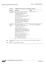
Service State
(Display only) Identifies the autonomously
generated state that gives the overall condition
of the port. Service states appear in the format:
Primary State-Primary State Qualifier,
Secondary State. For more information about
service states, see
Administrative and Service States.”
•
IS-NR/Unlocked-enabled
•
OOS-AU,AINS/Unlocked-disabled,automaticInService
•
OOS-MA,DSBLD/Locked-enabled,disabled
•
OOS-MA,MT/Locked-enabled,maintenance
Line Direction
(Display only) Displays the line direction
associated with the port. The parameter is
automatically configured during ANS.
From the drop-down list, choose one of the following:
•
East to West
•
West to East
Type
(Display only) Port type
•
Add
•
Passthrough
Power
(Display only) Power value read by the
photodiode located after the VOA associated to
the port, and calibrated to the COM_TX port.
For more information, see the
and the
“B.4.15 32WSS Card Specifications” section
on page B-32
.
Numeric value (dB)
Summary of Contents for ONS 15454 DWDM
Page 38: ...Figures xxxviii Cisco ONS 15454 DWDM Installation and Operations Guide R6 0 August 2005 ...
Page 54: ...Procedures liv Cisco ONS 15454 DWDM Installation and Operations Guide R6 0 August 2005 ...
Page 64: ... 64 Cisco ONS 15454 DWDM Installation and Operations Guide R6 0 August 2005 Chapter ...


