15-31
Cisco ONS 15454 DWDM Installation and Operations Guide, R6.0
September 2005
Chapter 15 Shelf Hardware Reference
15.9 ONS 15454 ANSI Alarm Expansion Panel
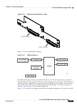
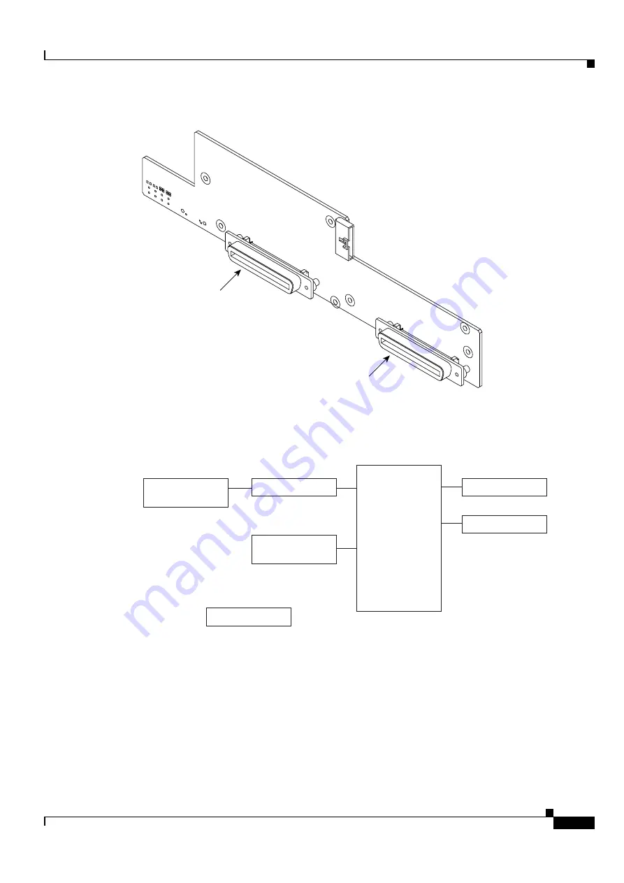
Figure 15-29
AEP Printed Circuit Board Assembly
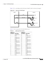
shows the AEP block diagram.
Figure 15-30
AEP Block Diagram
Each AEP alarm input port has provisionable label and severity. The alarm inputs have optocoupler
isolation. They have one common 32-VDC output and a maximum of 2 mA per input. Each opto-metal
oxide semiconductor (MOS) alarm output can operate by definable alarm condition, a maximum open
circuit voltage of 60 VDC, and a maximum current of 100 mA. See the
Controls” section on page 23-12
for further information.
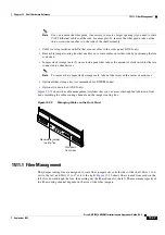
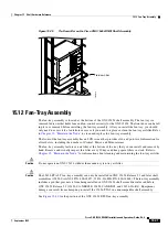
shows the wire-wrapping connections on the shelf backplane used to connect to the AEP.
78471
Input Connector
Output Connector
AIC-I Interface
(wire wrapping)
TIA/EIA 485
In Alarm Relays
Out Alarm Relays
Inventory data
(EEPROM)
AEP/AIE
CPLD
Power Supply
78406
Summary of Contents for ONS 15454 DWDM
Page 38: ...Figures xxxviii Cisco ONS 15454 DWDM Installation and Operations Guide R6 0 August 2005 ...
Page 54: ...Procedures liv Cisco ONS 15454 DWDM Installation and Operations Guide R6 0 August 2005 ...
Page 64: ... 64 Cisco ONS 15454 DWDM Installation and Operations Guide R6 0 August 2005 Chapter ...


