16-84
Cisco ONS 15454 DWDM Installation and Operations Guide, R6.0
April 2006
Chapter 16 Card Reference
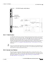
16.8.2 TXP_MR_10E Card
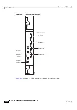
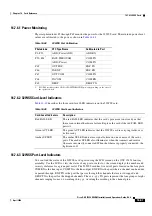
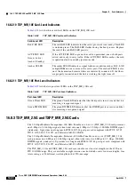
16.8.1.3 TXP_MR_10G Card-Level Indicators
lists the three card-level LEDs on the TXP_MR_10G card.
16.8.1.4 TXP_MR_10G Port-Level Indicators
lists the four port-level LEDs in the TXP_MR_10G card.
16.8.2 TXP_MR_10E Card
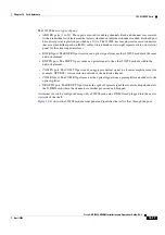
The 10-Gbps Transponder–100-GHz–Tunable xx.xx-xx.xx (TXP_MR_10E) card is a multirate
transponder for the ONS 15454 platform. The card is fully backward compatible with the TXP_MR_10G
card. It processes one 10-Gbps signal (client side) into one 10-Gbps, 100-GHz DWDM signal (trunk
side) that is tunable over four wavelength channels (spaced at 100 GHz on the ITU grid) in the C-band
and tunable over eight wavelength channels (spaced at 50 GHz on the ITU grid) in the L-band. There are
eight versions of the C-band card, with each version covering four wavelengths, for a total coverage of
32 wavelengths. There are five versions of the L-band card, with each version covering eight
wavelengths, for a total coverage of 40 wavelengths.
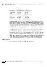
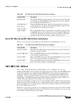
Table 16-50
TXP_MR_10G Card-Level Indicators
Card-Level LED
Description
FAIL LED (Red)
Red indicates that the card’s processor is not ready. This LED is on during
reset. The FAIL LED flashes during the boot process. Replace the card if the
red FAIL LED persists.
ACT/STBY LED
Green (Active)
Amber (Standby)
Green indicates that the card is operational (one or both ports active) and
ready to carry traffic.
Amber indicates that the card is operational and in standby (protect) mode.
SF LED (Amber)
Amber indicates a signal failure or condition such as LOS, LOF, or high
BERs on one or more of the card’s ports. The amber SF LED is also
illuminated if the transmit and receive fibers are incorrectly connected. If the
fibers are properly connected and the link is working, the LED turns off.
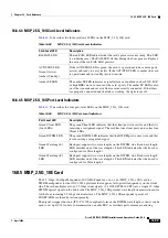
Table 16-51
TXP_MR_10G Port-Level Indicators
Port-Level LED
Description
Green Client LED
The green Client LED indicates that the client port is in service and that it is
receiving a recognized signal.
Green DWDM LED
The green DWDM LED indicates that the DWDM port is in service and that
it is receiving a recognized signal.
Green Wavelength 1
LED
Each port supports two wavelengths on the DWDM side. Each wavelength
LED matches one of the wavelengths. This LED indicates that the card is
configured for Wavelength 1.
Green Wavelength 2
LED
Each port supports two wavelengths on the DWDM side. Each wavelength
LED matches one of the wavelengths. This LED indicates that the card is
configured for Wavelength 2.
Summary of Contents for ONS 15454 DWDM
Page 38: ...Figures xxxviii Cisco ONS 15454 DWDM Installation and Operations Guide R6 0 August 2005 ...
Page 54: ...Procedures liv Cisco ONS 15454 DWDM Installation and Operations Guide R6 0 August 2005 ...
Page 64: ... 64 Cisco ONS 15454 DWDM Installation and Operations Guide R6 0 August 2005 Chapter ...

