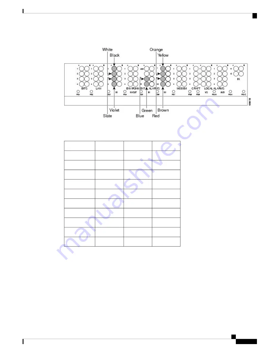
Figure 46: AEP Wire-Wrap Connections to Backplane Pins
The following table shows the backplane pin assignments and corresponding signals on the AIC-I and AEP.
Table 8: Pin Assignments for the AEP
AEP Signal
AIC-I Signal
Backplane Pin
AEP Cable Wire
AEP_GND
GND
A1
Black
AEP_+5
AE_+5
A2
White
VBAT–
VBAT–
A3
Slate
VB+
VB+
A4
Violet
AE_CLK_P
AE_CLK_P
A5
Blue
AE_CLK_N
AE_CLK_N
A6
Green
AE_DOUT_P
AE_DIN_P
A7
Yellow
AE_DOUT_N
AE_DIN_N
A8
Orange
AE_DIN_P
AE_DOUT_P
A9
Red
AE_DIN_N
AE_DOUT_N
A10
Brown
The following figure is a circuit diagram of the alarm inputs. (Inputs 1 and 48 are shown in the example.)
Cisco ONS 15454 Hardware Installation Guide
87
Installing the ONS 15454 M12 (ANSI and ETSI) Shelf
ONS 15454 ANSI Alarm Expansion Panel
Summary of Contents for ONS 15454
Page 2: ... 2019 Cisco Systems Inc All rights reserved ...
Page 16: ...Cisco ONS 15454 Hardware Installation Guide xvi Contents ...
Page 28: ...Cisco ONS 15454 Hardware Installation Guide xxviii Preface Preface ...
Page 36: ...Cisco ONS 15454 Hardware Installation Guide 6 Overview Cisco ONS 15454 M6 Shelf ...
Page 510: ...Cisco ONS 15454 Hardware Installation Guide 480 Hardware Specifications Dimensions ...


