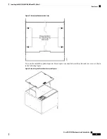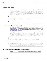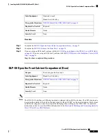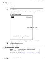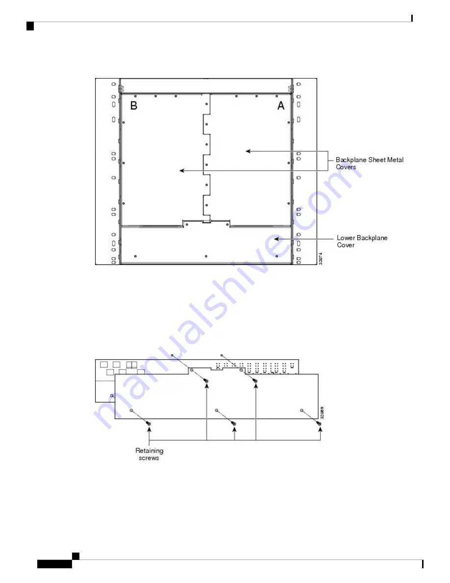
Figure 29: Backplane Covers
Lower Backplane Cover
The lower section of the ONS 15454 ANSI backplane is covered by either a clear plastic protector
(15454-SA-ANSI) or a sheet metal cover (15454-SA-HD), which is held in place by five 6-32 x 1/2 inch
screws. Remove the lower backplane cover to access the alarm interface panel (AIP), alarm pin fields, frame
ground, and power terminals.
Figure 30: Removing the Lower Backplane Cover
Rear Cover
The ONS 15454 ANSI has an optional clear plastic rear cover. This clear plastic cover provides additional
protection for the cables and connectors on the backplane.
Cisco ONS 15454 Hardware Installation Guide
54
Installing the ONS 15454 M12 (ANSI and ETSI) Shelf
Lower Backplane Cover
Summary of Contents for ONS 15454
Page 2: ... 2019 Cisco Systems Inc All rights reserved ...
Page 16: ...Cisco ONS 15454 Hardware Installation Guide xvi Contents ...
Page 28: ...Cisco ONS 15454 Hardware Installation Guide xxviii Preface Preface ...
Page 36: ...Cisco ONS 15454 Hardware Installation Guide 6 Overview Cisco ONS 15454 M6 Shelf ...
Page 510: ...Cisco ONS 15454 Hardware Installation Guide 480 Hardware Specifications Dimensions ...


