1-39
Cisco ONS 15454 DWDM Procedure Guide, Release 9.2
78-19286-01
Chapter 1 Install the Cisco ONS 15454 Shelf Assembly
Required Tools and Equipment (ETSI)
Step 7
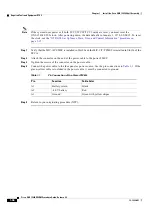
Terminate the return 1 lead to the RET1 backplane terminal. Use oxidation-prevention grease to keep the
connections noncorrosive.
Step 8
Terminate the negative 1 lead to the negative BAT1 backplane power terminal. Use oxidation prevention
grease to keep connections noncorrosive.
Step 9
If you use redundant power leads, terminate the return 2 lead to the positive RET2 terminal on the
ONS 15454. Terminate the negative 2 lead to the negative BAT2 terminal on the ONS 15454. Use
oxidation-preventative grease to keep connections noncorrosive.
Step 10
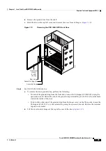
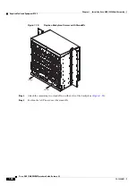
Route the cables out below the power terminals using the plastic cable clamp, as shown in
.
Step 11
Return to your originating procedure (NTP).
DLP-G19 Turn On and Verify Office Power
Caution
Do not apply power to the shelf assembly until you complete all installation steps.
Step 1
Using a voltmeter, verify the office battery and ground at the following points on the fuse and alarm
panel:
a.
To verify the power, place the black test lead of the voltmeter to the frame ground. Place the red test
lead on the A-side connection and verify that it is between –40.5 VDC and –57 VDC. Place the red
test lead on the B-side connection and verify that it is between –40.5 VDC and –57 VDC.
Note
The voltages –40.5 VDC and –57 VDC are, respectively, the minimum and maximum
voltages required to power the chassis. The nominal steady-state voltage is -48 VDC.
b.
To verify the ground, place the black test lead of the voltmeter to the frame ground. Place the red
test lead on the A-side return ground and verify that no voltage is present. Place the red test lead on
the B-side return ground and verify that no voltage is present.
Step 2
To power up the node, insert the fuse into the fuse position according to site practice. The fuse rating
must not exceed 30A.
Purpose
This task measures the power to verify correct power and returns for the ONS
15454 shelf.
Tools/Equipment
Voltmeter
Prerequisite
Procedures
ETSI:
•
Connect the office ground to chassis. For detailed instructions on
grounding, refer to the
Cisco ONS Electrostatic Discharge (ESD) and
•
DLP-G17 Connect Office Power to the ONS 15454 ETSI, page 1-35
•
DLP-G18 Connect Office Power to the ONS 15454 ANSI, page 1-37
Required/As Needed Required
Onsite/Remote
Onsite
Security Level
None
Summary of Contents for ONS 15454
Page 48: ...Tables xlviii Cisco ONS 15454 DWDM Procedure Guide Release 9 2 78 19286 01 ...
Page 58: ...Procedures lviii Cisco ONS 15454 DWDM Procedure Guide Release 9 2 78 19286 01 ...
Page 78: ...Tasks lxxviii Cisco ONS 15454 DWDM Procedure Guide Release 9 2 78 19286 01 ...
Page 85: ...lxxxv Cisco ONS 15454 DWDM Procedure Guide Release 9 2 78 19286 01 Preface ...
Page 87: ...lxxxvii Cisco ONS 15454 DWDM Procedure Guide Release 9 2 78 19286 01 Preface ...

