10
PA-2JT2 6.3-MHz Serial Port Adapter Installation and Configuration
OL-3587-01
What Is the JT2 Port Adapter?
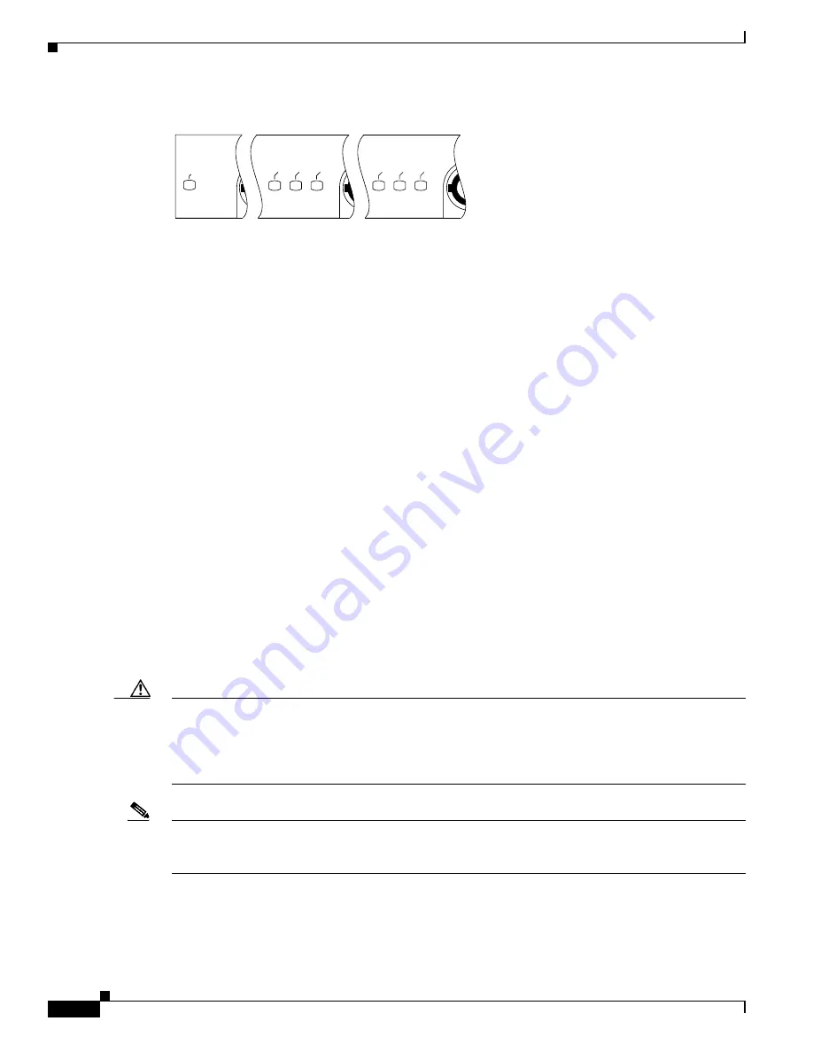
Figure 4
LEDs on the JT2 Port Adapter (Partial Front-Panel View)
The following conditions must be met before the enabled LED goes on:
•
The JT2 port adapter is correctly connected and receiving power.
•
The VIP2 contains a valid microcode version that has been downloaded successfully.
•
The bus recognizes the VIP2 attached to the backplane.
If any of these conditions is not met, or if the initialization fails for other reasons, the enabled LED
does not go on. The JT2 port adapter has three additional status LEDs for each JT2 port, which are
labeled and function as follows:
•
AIS—This red alarm indication signal LED indicates physical layer AIS when all ones are detected
in the received bit stream.
•
RAI—This red remote alarm indication LED indicates the presence of 16 or more repeating RAI bit
patterns (1111111100000000) present on the receive data channel. Recovery occurs when four or
more consecutive patterns occur, which are not the RAI pattern received.
•
LOS—This red loss of signal LED indicates that a loss of signal has occurred on the receive data
line when input data is zero for 20–32 consecutive clock cycles. Recovery occurs when the receive
signal returns.
JT2 Port Adapter Interface Connectors and Cables
The interface connectors on the JT2 port adapter are coaxial BNC types, with one connector/cable for
transmit (TX) and one for receive (RX) for each interface port. Each BNC connection requires an
external B-type or C-type DSU (with external grounding capability), with an optical fiber output, and
that uses 75-ohm BNC terminations. (Cisco Systems does not supply 75-ohm coaxial cables; they are
available from commercial cable vendors.)
Caution
Your coaxial cable’s loss must be less than 6 dB when using maximum cable lengths. To prevent
problems, you
must
check your 75-ohm coaxial cable’s specifications when long cable lengths are
required to connect the JT2 port adapter to your DSU. Unbalanced JT2 interfaces allow for a longer
maximum cable length than those specified for balanced circuits. Ideally, the maximum cable length for
unbalanced, 75-ohm coaxial cable is 1,968.5 feet (600 meters).
Note
The 75-ohm coaxial BNC connections must conform to JIS C5412-1976 high-frequency, coaxial
C02-type connectors, which are equivalent to MIL C 3608 BNC connectors and coaxial cables. The
cables must be unbalanced, 75-ohm (± 5% at 1 MHz) coaxial cables.
You must install a ferrite sleeve (also called a
common-mode choke
) on each 75-ohm coaxial cable to
reduce the effects of electro-magnetic interference (EMI). (Cisco Systems supplies four ferrite sleeves
with your JT2 port adapter; one ferrite sleeve for each of four 75-ohm coaxial cables you can attach to
PA-2JT2.)
ENABLED
AIS
RAI
LOS
AIS
RAI
LOS
H9371


