background image

Receptacles, Cables, and Pinouts

PA-FE-TX and PA-FE-FX Fast Ethernet 100BaseT Port Adapter Installation and Configuration

1-6

Figure 1-8 shows the RJ-45 cable connectors. Cisco Systems does not supply Category 5 UTP RJ-45
cables; these cables are available commercially. Table 1-1 lists the pinouts and signals for the
PA-FE-TX RJ-45 connectors.

Figure 1-8

PA-FE-TX RJ-45 Connections—Plug and Receptacle

Warning

The ports labeled “Ethernet,” “10BaseT,” “Token Ring,” “Console,” and “AUX” are

safety extra-low voltage (SELV) circuits. SELV circuits should only be connected to other SELV
circuits. Because the BRI circuits are treated like telephone-network voltage, avoid connecting the
SELV circuit to the telephone network voltage (TNV) circuits.

Table 1-1

PA-FE-TX RJ-45 Connector Pinout

Note

Referring to the RJ-45 pinout in Table 1-1, proper common-mode line terminations should be

used for the unused Category 5, UTP cable pairs 4/5 and 7/8. Common-mode termination reduces
the contributions to electromagnetic interference (EMI) and susceptibility to common-mode
sources. Wire pairs 4/5 and 7/8 are actively terminated in the RJ-45, 100BaseTX port circuitry in the
PA-FE-TX.

Depending on your RJ-45 interface cabling requirements, use the pinouts in Figure 1-9 and
Figure 1-10.

Figure 1-9

Straight-Through Cable Pinout—PA-FE-TX RJ-45 Connection to a Hub or
Repeater

Pin

Description

1

Receive Data + (RxD+)

2

RxD–

3

Transmit Data + (TxD+)

6

TxD–

H2936

8 7 6 5 4 3 2 1

RJ-45 connector

Hub or repeater

FEIP

3 TxD+

6 TxD–

1 RxD+

2 RxD–

3 RxD+

6 RxD–

1 TxD+

2 TxD–

H3137

Summary of Contents for PA-FE-FX

Page 1: ...rs PA FE TX and PA FE FX Platforms Supported Cisco 7200 Series Cisco 7000 Series and Cisco 7500 Series with VIP2 Cisco uBR7200 Series Cisco 7100 Series Note If you ordered this port adapter as a spare for your convenience Cisco has included a port adapter installation and configuration note for the Catalyst 5000 series Route Switch Module Versatile Interface Processor 2 RSM VIP2 Your port adapter ...

Page 2: ...lStream VisionWay VlanDirector Workgroup Director and Workgroup Stack are trademarks Changing the Way We Work Live Play and Learn Empowering the Internet Generation The Internet Economy and The New Internet Economy are service marks and Asist BPX Catalyst Cisco Cisco IOS the Cisco IOS logo Cisco Systems the Cisco Systems logo the Cisco Systems Cisco Press logo Enterprise Solver EtherChannel EtherS...

Page 3: ... Cisco uBR7200 series universal broadband routers which consist of the six slot four cable modem card slots and two port adapter slots Cisco uBR7246 and the three slot two cable modem card slots and one port adapter slot Cisco uBR7223 Cisco 7100 series routers which consist of the Cisco 7120 series and Cisco 7140 series Second generation Versatile Interface Processor VIP2 in all Cisco 7500 series ...

Page 4: ...or VIP2 users only Section Title Description Chapter 1 Overview Provides information about the PA FE TX and PA FE FX 100BaseT port adapters illustrates their location in the supported hardware platforms and describes their LED displays cables and receptacles Chapter 2 Preparing for Installation Provides information about safety considerations tools required and procedures you should perform before...

Page 5: ...ation Guide Cisco uBR7223 Universal Broadband Router Installation and Configuration Guide For international agency compliance safety and statutory information for interfaces for Cisco 7500 series routers Cisco 7000 series routers Cisco 7200 series routers Cisco 7100 series routers and Cisco uBR7200 series universal broadband routers refer to the following publications Regulatory Compliance and Saf...

Page 6: ...th America 408 526 8070 from Europe 33 1 64 46 40 82 Use the following terminal settings VT100 emulation databits 8 parity none stop bits 1 and connection rates up to 28 8 kbps For a copy of CCO s Frequently Asked Questions FAQ contact cco help cisco com For additional information contact cco team cisco com If you are a network administrator and need personal technical assistance with a Cisco prod...

Page 7: ... Mbps 100BaseT Fast Ethernet interface and support both full duplex and half duplex operation Refer to the Fast Ethernet Overview section on page 1 9 for additional information Figure 1 1 shows the PA FE TX and Figure 1 2 shows the PA FE FX Note While the VIP2 supports online insertion and removal OIR individual port adapters do not To replace port adapters you must first remove the VIP2 from the ...

Page 8: ...7223 Cisco 7100 series Port adapter slot 3 Note Port adapters have a handle attached but this handle is occasionally not shown to allow a full view of detail on the port adapter s faceplate Port Adapter Locations on the Supported Platforms Figure 1 3 and Figure 1 4 show VIP2 models with installed port adapters With the VIP2 oriented as shown in Figure 1 3 or Figure 1 4 the left port adapter is in ...

Page 9: ...lable with or without a Fast Ethernet port You can install both I O controller types in all Cisco 7200 series routers however when you install an I O controller with a Fast Ethernet port in a Cisco 7202 the system software automatically disables the port Figure 1 5 shows a Cisco 7206 with installed port adapters and an I O controller with a Fast Ethernet port Not shown are the Cisco 7202 which has...

Page 10: ... Cisco uBR7246 H6422 2 ETHERNET 10BT EN AB LE D 0 2 1 3 LI NK 0 1 2 3 E N A B LE D M II L IN K R J4 5 FAST ETHERNET 0 0 4 1 3 5 6 Port adapter slot 5 Port adapter slot 3 Port adapter slot 1 FAST SERIAL EN TD TC RD RC LB CD TD TC RD RC LB CD TD TC RD RC LB CD TD TC RD RC LB CD TOKEN RING 0 1 2 3 ETHERNET 10BFL E N R X 0 1 2 3 4 T X R X T X R X T X R X T X R X T X Blank port adapter Port adapter slo...

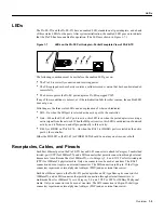
Page 11: ...cation of network activity and it flickers on and off proportionally to this activity RJ 45 or FIBER on PA FE FX On when the RJ 45 or FIBER port is selected as the active port by the controller Either the MII LED or the RJ 45 or FIBER LED should be on at any one time never both Receptacles Cables and Pinouts Each Fast Ethernet port on the PA FE TX has an RJ 45 connector to attach to Category 5 uns...

Page 12: ...ting the SELV circuit to the telephone network voltage TNV circuits Table 1 1 PA FE TX RJ 45 Connector Pinout Note Referring to the RJ 45 pinout in Table 1 1 proper common mode line terminations should be used for the unused Category 5 UTP cable pairs 4 5 and 7 8 Common mode termination reduces the contributions to electromagnetic interference EMI and susceptibility to common mode sources Wire pai...

Page 13: ...the port adapter The port adapters are field replaceable units FRUs The MII receptacle uses 2 56 screw type locks called jackscrews shown in Figure 1 13 to secure the cable or transceiver to the MII port MII cables and transceivers have knurled thumbscrews that you fasten to the jackscrews on the PA FE TX s MII connector Use the jackscrews to provide strain relief for your MII cable Figure 1 13 sh...

Page 14: ...ceiver and your network can be Category 3 4 or 5 150 ohm UTP or FTP or multimode optical fiber Table 1 2 MII Connector Pinout Pin1 1 Any pins not indicated are not used In Out In Out Description 14 17 Yes Transmit Data TxD 12 Yes Transmit Clock Tx_CLK 2 2 Tx_CLK and Rx_CLK are generated by the external transceiver 11 Yes Transmit Error Tx_ER 13 Yes Transmit Enable Tx_EN 3 Yes MII Data Clock MDC 4 ...

Page 15: ... to determine when they should retransmit Both Ethernet and IEEE 802 3u are broadcast networks which means that all stations see all transmissions Each station must examine received frames to determine whether it is the intended destination and if it is pass the frame to a higher protocol layer for processing IEEE 802 3u specifies the following different physical layers for 100BaseT 100BaseTX 100B...

Page 16: ...II cables Both are available commercially Category 3 4 or 5 150 ohm UTP or FTP or multimode optical fiber 62 5 125 multimode optical fiber Maximum cable length 1 64 ft 0 5 m MII to MII cable3 3 This is the cable between the MII port on the PA FE port adapter and the appropriate transceiver Maximum segment length 328 ft 100 m for 100BaseTX 3 28 ft 1 m 4 or 1 312 ft 400 m for 100BaseFX 4 This length...

Page 17: ... FE TX or PA FE FX port adapter and one of the following VIP2 15 VIP2 20 VIP2 40 or VIP2 50 For specific VIP2 model information see the Software and Hardware Requirements section on page 2 2 Cisco 7100 series router with at least one available port adapter slot Cisco 7200 series router with at least one available port adapter slot Cisco uBR7200 series universal broadband router with at least one a...

Page 18: ...e 11 1 16 CA or a later release of Cisco IOS Release 11 1 CA Cisco IOS Release 11 2 1 or a later release of Cisco IOS Release 11 2 Cisco IOS Release 11 2 5 P or a later release of Cisco IOS Release 11 2 P With VIP2 50 Cisco IOS Release 11 1 14 CA or a later release of Cisco IOS Release 11 1 CA Cisco 7200 series Cisco 7204VXR and Cisco 7206VXR Cisco IOS Release 12 0 2 XE2 or a later release of Cisc...

Page 19: ...varoitusmerkki merkitsee vaaraa Olet tilanteessa joka voi johtaa ruumiinvammaan Ennen kuin työskentelet minkään laitteiston parissa ota selvää sähkökytkentöihin liittyvistä vaaroista ja tavanomaisista onnettomuuksien ehkäisykeinoista Tässä julkaisussa esiintyvien varoitusten käännökset löydät laitteen mukana olevasta Regulatory Compliance and Safety Information kirjasesta määräysten noudattaminen ...

Page 20: ...tándar de prevención de accidentes Para ver una traducción de las advertencias que aparecen en esta publicación consultar el documento titulado Regulatory Compliance and Safety Information Información sobre seguridad y conformidad con las disposiciones reglamentarias que se acompaña con este dispositivo Varning Denna varningssymbol signalerar fara Du befinner dig i en situation som kan leda till p...

Page 21: ...hassis surface When installing a component use any available ejector levers or captive installation screws to properly seat the bus connectors in the backplane or midplane These devices prevent accidental removal provide proper grounding for the system and help to ensure that bus connectors are properly seated When removing a component use any available ejector levers or captive installation screw...

Page 22: ...articular installation You can determine whether your equipment is causing interference by turning it off If the interference stops it was probably caused by the Cisco equipment or one of its peripheral devices If the equipment causes interference to radio or television reception try to correct the interference by using one or more of the following measures Turn the television or radio antenna unt...

Page 23: ...system is operating To install or replace port adapters first remove the VIP2 from its interface processor slot Note Each port adapter circuit board is mounted to a metal carrier and is sensitive to ESD damage Each port adapter has one Phillips head screw that secures it to its port adapter slot We strongly recommend that the following procedures be performed by a Cisco certified service provider ...

Page 24: ... Figure 3 2 shows a PA FE FX installed in port adapter slot 0 on a VIP2 15 or VIP2 40 Figure 3 1 VIP2 15 or VIP2 40 with a PA FE TX in Port Adapter Slot 0 Note The PA FE FX has the MII connector like the PA FE TX but has an SC type fiber optic connector in place of the RJ 45 connector H6449 PA FE TX in port adapter slot 0 Port adapter blank in port adapter slot 1 Port adapter handles not shown Bus...

Page 25: ...0 on a VIP2 50 Figure 3 3 VIP2 50 with an PA FE TX in Port Adapter Slot 0 H6453 0 FAST ETHERNET F IB E R L IN K M II M I I L I N K F I B E R Bus connector DRAM SIMMs SRAM DIMM U5 PA FE FX in portadapter slot 0 CPU U6 U2 U4 Port adapter handles not shown Port adapter blank in port adapter slot 1 Boot ROM Blank port adapter in slot 1 H10470 PA FE TX port adapter in slot 0 CPU Bus connector SRAM daug...

Page 26: ...ou must first remove the blank port adapter from the port adapter slot in which you want to install the new port adapter Step 2 For a new port adapter installation or a port adapter replacement disconnect any interface cables from the ports on the front of the port adapter although this is not required You can remove VIP2s with cables attached however we do not recommend it Step 3 Remove the VIP2 ...

Page 27: ...rew removed grasp the handle on the front of the port adapter or blank port adapter and carefully pull it out of its slot away from the edge connector at the rear of the slot See Figure 3 6 Figure 3 6 Pulling a Port Adapter Out of a Slot Partial Port Adapter Step 7 If you removed a port adapter place it in an antistatic container for safe storage or shipment back to the factory If you removed a bl...

Page 28: ...fully align the port adapter carrier between the upper and lower edges of the port adapter slot as shown in Figure 3 7 Figure 3 7 Installing a New Port Adapter Caution To prevent jamming the carrier between the upper and lower edges of the port adapter slot and to ensure that the edge connector at the rear of the port adapter seats in the connector at the rear of the port adapter slot make certain...

Page 29: ...is screw Step 6 Reinstall the VIP2 in the system To do so follow the steps in the section Installing a VIP2 in the configuration note Second Generation Versatile Interface Processor VIP2 Installation and Configuration which shipped with your VIP2 Step 7 If the interface cables are disconnected reconnect the interface cables to the port adapters This completes the procedure for installing any type ...

Page 30: ...Installing a Port Adapter PA FE TX and PA FE FX Fast Ethernet 100BaseT Port Adapter Installation and Configuration 3 8 ...

Page 31: ...all port adapters available for the Cisco 7200 series routers connect directly to the router midplane and are locked into position by a port adapter lever When removing and replacing a port adapter you need an antistatic mat onto which you can place a removed port adapter and an antistatic container into which you can place a failed port adapter for shipment back to the factory Note Cisco 7200 ser...

Page 32: ...ed port adapter slot in the unlocked position The lever remains in the unlocked position See Figure 4 3 H6786 ETHERNET 10BT EN AB LE D 0 2 1 3 LI NK 0 1 2 3 FAST SERIAL EN TD TC RD RC LB CD TD TC RD RC LB CD TD TC RD RC LB CD TD TC RD RC LB CD E N A B LE D M II L IN K R J4 5 FAST ETHERNET 0 TOKEN RING 0 1 2 3 0 2 4 1 3 5 6 ETHERNET 10BFL E N R X 0 1 2 3 4 T X R X T X R X T X R X T X R X T X FAST E...

Page 33: ...ever touch the port adapter s components or connector pins See Figure 4 4 Figure 4 4 Handling a Port Adapter Step 6 Place the port adapter on an antistatic surface with its components facing upward or in a static shielding bag If the port adapter will be returned to the factory immediately place it in a static shielding bag This completes the procedure for removing a port adapter from a Cisco 7200...

Page 34: ...ay into the slot Caution Do not slide the port adapter all the way into the slot until you have connected all required cables Trying to do so disrupts normal operation of the router Step 5 With the port adapter halfway in the slot connect all required cables to the port adapter Step 6 After connecting the cables carefully slide the port adapter all the way into the slot until you feel the port ada...

Page 35: ...es to your port adapter ETHERNET 10BT EN AB LE D 0 2 1 3 LI NK 0 1 2 3 FAST SERIAL EN TD TC RD RC LB CD TD TC RD RC LB CD TD TC RD RC LB CD TD TC RD RC LB CD E N A B LE D M II L IN K R J4 5 FAST ETHERNET 0 TOKEN RING 0 1 2 3 0 2 4 1 3 5 6 H6747 M II E N R J 4 5 E N R J 4 5 L IN K 1 O P W R O K R J 45 C P U R E S E T FAST ETHERNET INPUT OUTPUT CONTROLLER E N A B L E D P C M C IA E J E C T S L O T 0...

Page 36: ...Installing a Port Adapter PA FE TX and PA FE FX Fast Ethernet 100BaseT Port Adapter Installation and Configuration 4 6 ...

Page 37: ...ention clip Cisco UBR7246 When removing and replacing a port adapter you need an antistatic mat onto which you can place a removed port adapter and an antistatic container into which you can place a failed port adapter for shipment back to the factory Note Cisco uBR7200 series universal broadband routers support online insertion and removal OIR therefore you do not have to power down the routers w...

Page 38: ...Cisco uBR7200 series universal broadband router Step 1 Attach an ESD preventive wrist strap between you and an unfinished chassis surface Warning During this procedure wear grounding wrist straps to avoid ESD damage to the card Do not directly touch the backplane with your hand or any metal tool or you could shock yourself Step 2 Unlock the retaining mechanism of the port adapter For a Cisco uBR72...

Page 39: ...r from the router midplane about halfway out of its slot If you are removing a blank port adapter pull the blank port adapter completely out of the chassis slot Note As you disengage the port adapter from the router midplane OIR administratively shuts down all active interfaces on the port adapter Step 4 With the port adapter halfway out of the slot disconnect all cables from the port adapter Step...

Page 40: ...co uBR7200 series universal broadband router Installing a Port Adapter Use the following procedure to install a new port adapter in a Cisco uBR7200 series universal broadband router Step 1 Attach an ESD preventive wrist strap between you and an unfinished chassis surface Warning During this procedure wear grounding wrist straps to avoid ESD damage to the card Do not directly touch the backplane wi...

Page 41: ...les to the port adapter Step 6 After connecting the cables carefully slide the port adapter all the way into the slot until you feel the port adapter s connectors make contact with the midplane Step 7 For a Cisco uBR7246 slide the port adapter retention clip to the locked position Figure 5 7 shows the retention clip in the locked position Note If the retention clip does not slide up to the locked ...

Page 42: ...oes not move to the locked position the port adapter is not completely seated in the midplane Carefully pull the port adapter halfway out of the slot reinsert it and move the port adapter lever to the locked position This completes the procedure for installing a new port adapter or replacing a port adapter in a Cisco uBR7200 series universal broadband router Proceed to Chapter 7 Installing PA FE P...

Page 43: ...nstalling a Port Adapter page 6 3 Installation Overview The PA FE TX and PA FE FX can be installed in port adapter slot 3 in the Cisco 7120 series and in port adapter slot 4 in the Cisco 7140 series Figure 6 1 shows port adapter slot 3 of a Cisco 7120 series router Figure 6 2 shows port adapter slot 4 of a Cisco 7140 series router Figure 6 1 Cisco 7120 Series Router Port Adapter Slot 3 Location SL...

Page 44: ...t in use you must first remove a blank port adapter Removing a Port Adapter Use the following procedure to remove a port adapter from a Cisco 7100 series router Step 1 Attach an ESD preventive wrist strap between you and the chassis See Figure 6 1 or Figure 6 2 for the location of the ESD plug Step 2 Use a number 2 Phillips screwdriver to loosen the screws on the locking tab then slide the tab dow...

Page 45: ...BLANK This completes the procedure for removing a port adapter from a Cisco 7100 series router Installing a Port Adapter Use the following procedure to install a new port adapter in a Cisco 7100 series router Step 1 Attach an ESD preventive wrist strap between you and the chassis See Figure 6 1 or Figure 6 2 for the location of the ESD plug Step 2 Ensure that the locking tab is down in the unlocke...

Page 46: ... slot until the port adapter is seated in the router Step 9 After seating the port adapter in the router slide the locking tab up to the locked position and tighten the screws Figure 6 1 or Figure 6 2 shows the locking tab in the locked position Note If the port adapter lever is not in the locked position the port adapter is not completely seated in the router Carefully pull the port adapter halfw...

Page 47: ...of the IEEE 802 3u specification otherwise interface problems might result Confirm that this capability is available on your MII transceiver with the transceiver s vendor or in the transceiver s documentation If a selection for Isolation Mode is available we recommend you use this setting if no mention is made of PHY addressing Attaching PA FE Port Adapter Interface Cables Use the following proced...

Page 48: ...necting PA FE TX MII or RJ 45 Cables Horizontal Orientation Shown Without Handles Figure 7 2 Connecting PA FE FX MII or SC Cables Horizontal Orientation Shown Without Handles Warning Because invisible laser radiation may be emitted from the aperture of the port when no cable is connected avoid exposure to laser radiation and do not stare into open apertures H5920 MII cable To transceiver repeater ...

Page 49: ...nection can be used at one time Only connect cables that comply with EIA TIA 568 standards See Table 1 1 and Table 1 2 in the Receptacles Cables and Pinouts section on page 1 5 for cable recommendations and specifications Step 3 Attach the network end of your RJ 45 SC or MII cable to your 100BaseT transceiver switch hub repeater DTE or other external 100BaseT equipment Note After your MII transcei...

Page 50: ...Attaching PA FE Port Adapter Interface Cables PA FE TX and PA FE FX Fast Ethernet 100BaseT Port Adapter Installation and Configuration 7 4 ...

Page 51: ...cision about the use of bridging on the new interfaces The configure command requires privileged level access to the EXEC command interpreter which usually requires a password Contact your system administrator if necessary to obtain EXEC level access For a summary of the configuration options available and instructions for configuring the Fast Ethernet interfaces on the supported platforms refer t...

Page 52: ...r the correct password the system displays the privileged level system prompt Router If you installed a new PA FE or if you want to change the configuration of an existing interface you must enter configuration mode using the configuration command If you replaced an interface that was previously configured the system recognizes the new interface and brings it up in its existing configuration Ident...

Page 53: ... series routers port adapter slots are numbered from the lower left to the upper right beginning with port adapter slot 1 and continuing through port adapter slot 2 for the Cisco 7202 slot 4 for the Cisco 7204 and Cisco 7204VXR and slot 6 for the Cisco 7206 and Cisco 7206VXR Port adapter slot 0 is reserved for the optional Fast Ethernet port on the I O controller if present Figure 8 1 shows the in...

Page 54: ...er of ports on a port adapter Figure 8 2 Cisco uBR7200 Series Fast Ethernet Interface Port Number Example Cisco uBR7246 You can identify interface ports by physically checking the slot interface port location on the front of the router or by using show commands to display information about a specific interface or all interfaces in the router VIP2 Ports On the VIP2 installed in Cisco 7500 series or...

Page 55: ...ce processor slot 2 the address of this FE port becomes 2 0 0 Figure 8 3 Fast Ethernet Interface Port Number Example Cisco 7505 You can also identify interface ports by physically checking the slot port adapter interface port location on the back of the router or by using software commands to display information about a specific interface or all interfaces in the router Cisco 7100 Series Ports In ...

Page 56: ...ols you plan to route on the interface For more information on FE interface configurations on supported platforms refer to the modular configuration and modular command reference publications in the Cisco IOS software configuration documentation set that corresponds to the software release installed on your Cisco hardware In the following procedure press the Return key after each step unless other...

Page 57: ...lf 5 For the VIP2 at the prompt specify the first interface to configure by entering the subcommand interface followed by the type fastethernet and slot port adapter interface The example that follows is for the first interface of the first port adapter on a VIP2 in interface processor slot 1 Router config interface fastethernet 1 0 0 Step 3 If IP routing is enabled on the system you can assign an...

Page 58: ...et command to verify that the 4 0 Fast Ethernet interface is now configured for half duplex operation as follows Router show interfaces fastethernet 4 0 FastEthernet2 0 is administratively up line protocol is up display text omitted Encapsulation ARPA loopback not set keepalive not set hdx 100BaseTX display text omitted To check the interface configuration using show commands proceed to the Checki...

Page 59: ... new interfaces as follows For the Cisco 7100 Cisco 7200 series and the Cisco uBR7200 series specify one of the new interfaces with the show interfaces port adapter type slot interface command and verify that the first line of the display specifies the interface with the correct slot number Also verify that the interface and line protocol are in the correct state up or down Note For the Cisco 7206...

Page 60: ...P Timeout 4 00 00 Last input 3 08 43 output 3 08 42 output hang never Last clearing of show interfaces counters 2 58 36 Output queue 0 40 0 drops input queue 0 75 0 drops 5 minute input rate 0 bits sec 0 packets sec 5 minute output rate 0 bits sec 0 packets sec 0 packets input 0 bytes 0 no buffer Received 0 broadcasts 0 runts 0 giants 0 input errors 0 CRC 0 frame 0 overrun 0 ignored 0 abort 0 watc...

Page 61: ...s 0x2 Use the show diag slot command to determine which type of port adapter is installed in your system Specific port adapter information is displayed as shown in the following example of a PA FE FX in port adapter slot 2 Router show diag 2 Slot 2 Fast ethernet port adapter 1 port Port adapter is analyzed Port adapter insertion time 2d09h ago Hardware revision 255 255 Board revision A0 Serial num...

Page 62: ...bytes 0 underruns 0 output errors 0 collisions 0 interface resets 0 restarts 0 babbles 0 late collision 0 deferred 0 lost carrier 0 no carrier 0 output buffer failures 0 output buffers swapped out Use the show version command to display the configuration of the system hardware the number of each interface processor type installed the software version the names and sources of configuration files an...

Page 63: ...HW rev 1 0 Board revision 43 Serial number 02826254 Part number 73 1690 02 Proceed to the next section Using the ping Command to verify that each interface port is functioning properly Using the ping Command The ping command allows you to verify that an interface port is functioning properly and to check the path between a specific port and connected devices at various locations on the network Aft...

Page 64: ...te server with the address 172 16 0 0 Router ping 172 16 0 0 Type escape sequence to abort Sending 5 100 byte ICMP Echoes to 10 0 0 0 timeout is 2 seconds Success rate is 100 percent 5 5 round trip min avg max 1 15 64 ms Router If the connection fails verify that you have the correct IP address for the destination and that the device is active powered on and repeat the ping command ...

Reviews: