1-4
PA-MC-2T3+ Multi-Channel T3 Port Adapter Installation and Configuration
OL-3526-05
Chapter 1 Overview
LEDs
Note
The PA-MC-2T3+ does not support configuration of the far end T3 DSU using the maintenance data link
channel in c-bit parity framing.
LEDs
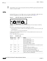
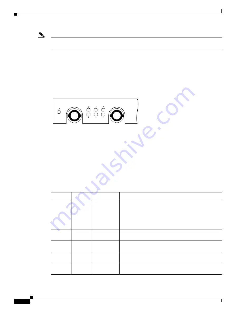
The PA-MC-2T3+ has seven status LEDs located on its faceplate: ENABLED, ALARM, LOOP, LOS,
OOF, AIS, and FERF. (These status LEDs are shown from left to right in
Figure 1-2
PA-MC-2T3+ Status LEDs—Partial Horizontal View
After system initialization, the green ENABLED LED indicates that the port adapter is enabled for
operation.
The following conditions must be met before the PA-MC-2T3+ is enabled:
•
The port adapter is correctly installed in the VIP motherboard or Cisco 7200 series router slot and
is receiving power.
•
The system software recognizes the PA-MC-2T3+
If either one of the preceding conditions is not met, or if the initialization fails for other reasons, the
enabled LED does not go on.
lists LED colors and indications.
22649
OOF
FERF
LOOP
ALRM
ENABLED
LOS
AIS
0
RX
TX
Table 1-3
PA-MC-2T3+ LEDs
LED Label
Color
State
Meaning
ALARM
Yellow
On
T1 loss of frame (LOF)
T1 alarm indication signal (AIS)
T3 loss of signal (LOS)
T3 alarm indication signal (AIS)
T3 out of frame (OOF)
T3 far-end received failure (FERF)
LOOP
Yellow
On
T1 line or T3 link in a loopback state; not enabled for normal
data traffic
LOS
Yellow
On
T3 link loss of the received signal.
Operates in conjunction with ALARM LED.
AIS
Yellow
On
T3 link receives alarm indication signal.
Operates in conjunction with the ALARM LED.
OOF
Yellow
On
Indicates a DS3 out-of-frame (OOF) condition. Operates in
conjunction with the ALARM LED.


