1-5
PA-MC-2T3+ Multi-Channel T3 Port Adapter Installation and Configuration
OL-3526-05
Chapter 1 Overview
Port Adapter Slot Locations on the Supported Platforms
In addition to the interface status information provided by the LEDs, you can also retrieve detailed
interface status information either through the router console port or through Telnet or Simple Network
Management Protocol (SNMP).
Port Adapter Slot Locations on the Supported Platforms
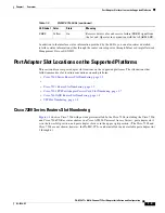
This section discusses port adapter slot locations on the supported platforms. The illustrations that
follow summarize slot location conventions on each platform:
•
Cisco 7200 Series Routers Slot Numbering, page 1-5
•
•
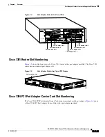
Cisco 7301 Router Slot Numbering, page 1-7
•
Cisco 7304 PCI Port Adapter Carrier Card Slot Numbering, page 1-7
•
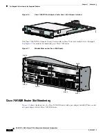
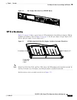
Cisco 7401ASR Router Slot Numbering, page 1-8
•
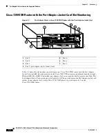
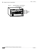
Cisco 7200 Series Routers Slot Numbering
shows a Cisco 7206 with port adapters installed. In the Cisco 7206 (including the Cisco 7206
and Cisco 7206VXR as router shelves in a Cisco AS5800 Universal Access Server), port adapter slot 1
is in the lower left position, and port adapter slot 6 is in the upper right position. (The Cisco 7202 and
Cisco 7204 are not shown; however, the PA-MC-2T3+ can be installed in any available port adapter slot
1 through 6.)
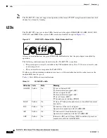
FERF
Yellow
On
Receiver detects a far end receive failure (FERF) signal from
the far end. Operates in conjunction with the ALARM LED.
Table 1-3
PA-MC-2T3+ LEDs (continued)
LED Label
Color
State
Meaning


