Chapter 2 Module Installation
38
78-4015908-01 Rev F
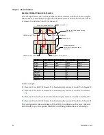
Example 2: Multiple Chassis Configuration
This example shows the control parameter values needed to define a more complex
Master-Slave relationship among four individual receiver channels in slots 6 and 27
of chassis 31 and slots 5 and 10 of chassis 11.
P
S
ICIM-out to ICIM-in cables, 2m long
(PN 180143)
HD-RxR in slot 5 (Slave)
HD-RxR in slot 10 (Master)
Prisma XD Chassis with ICIM
Prisma II Chassis (no ICIM)
ICIM bus terminator
(PN 4013014) required at end of
daisy chain.
HD-RxR in slot 6 (Slave)
HD-RxR in slot 27 (Master)
Control
Mode
Mode1
Mode2
Alarm1
Alarm2
Red1Chas
Red1Slot
Red1Sub
Red2Chas
Red2Slot
Red2Sub
Slot 5 Settings
Independent
Slave
Master
Off
Off
31
27
1
31
6
1
Slot 10 Settings
Independent
Slave
Master
Off
Off
31
27
2
31
6
2
Chassis ID = 11
Chassis ID = 31
Slot 6 Settings
Independent
Slave
Slave
Off
Off
11
5
2
11
10
2
Slot 27 Settings
Independent
Master
Master
Off
Off
11
5
1
11
10
1
In this example:
Receiver 1 in slot 27 of chassis 31 is backed up by receiver 1 in slot 5 of chassis 11.
Receiver 2 in slot 27 of chassis 31 is backed up by receiver 1 in slot 10 of chassis
11.
Receiver 2 in slot 5 of chassis 11 is backed up by receiver 1 in slot 6 of chassis 31.
Receiver 2 in slot 10 of chassis 11 is backed up by receiver 2 in slot 6 of chassis 31.
This configuration takes advantage of the ability to configure each receiver channel
individually to provide greater flexibility in defining Master-Slave relationships.

