background image

1200-Watt DC-Input Power Supply Replacement Instructions

Product Overview

Product Overview

The DC-input power supply is a modular power supply for the Cisco 7513 multiprotocol,
multimedia router. The DC-input power supply is optional equipment in the Cisco 7513. A second,
identical power supply, if installed, provides redundant power. Power supplies reside in power
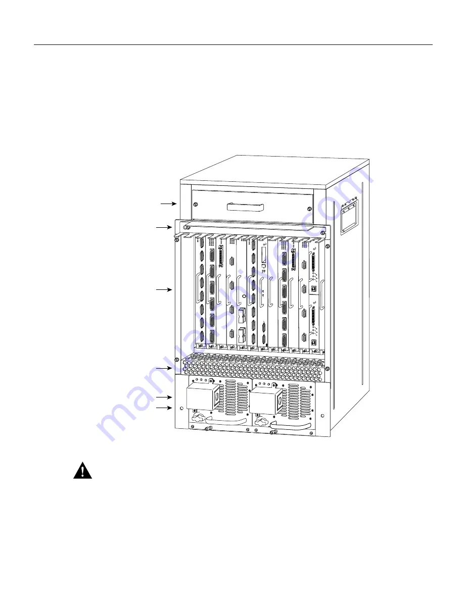
supply bays in the rear of the router chassis, as shown in Figure 1.

Figure 1

Cisco 7513—Rear-Panel View

Caution

 To prevent problems with the Cisco 7513, do not mix DC-input and AC-input power

supplies in the same chassis. Your Cisco 7513 must have either DC-input or AC-input power
supplies.

The power A bay contains the first (or standard) power supply, and the power B bay contains the
second (optional) supply in systems with redundant power.

ENABLE

ENABLE

H3162

0

I

OK

OK

FAIL

DC

FAN OUTPUT

0

I

OK

OK

FAIL

DC

FAN OUTPUT

EJECT

SLOT 0

SLOT 1

NORMAL

CPU HALT

RESET

AUX.

CONSOLE

ROUTE SWITCH PROCESSOR

POWER

B

POWER

A

Blower module

Cable management

bracket

Card cage and

processor modules

Air intake vent

Power supplies

Chassis grounding

receptacle (2)

Summary of Contents for PWR-7513-DC

Page 1: ... power supply when installed provides redundant power In systems with redundant power the power supplies are load sharing and fully hot swappable you can remove and replace one supply while the remaining supply immediately ramps up to full power to maintain uninterrupted system operation The sections in this document include the following Product Overview page 2 Installation Safety ESD Precautions...

Page 2: ...ar Panel View Caution To prevent problems with the Cisco 7513 do not mix DC input and AC input power supplies in the same chassis Your Cisco 7513 must have either DC input or AC input power supplies The power A bay contains the first or standard power supply and the power B bay contains the second optional supply in systems with redundant power ENABLE ENABLE H3162 0 I OK OK FAIL DC FAN OUTPUT 0 I ...

Page 3: ...vide full power and maintain uninterrupted power to the system Whenever possible connect each power supply to a separate DC source 1 VDC volts direct current Specification Rating DC input voltage 40 VDC1 minimum in North America 56 VDC in the European Community E C 48 VDC nominal at 33 amps A in North America 60 VDC at 26A in the E C 52 VDC maximum in North America 72 VDC in the E C Internal DC vo...

Page 4: ...ns Power supply DC output failure which could be caused by overload by the system or an actual failure in the DC input power Power shutdown initiated by the power supply because it detected an out of tolerance voltage condition in the power supply In systems with a single power supply and in systems with redundant power when both power supplies are shutting down the output fail LED lights momentar...

Page 5: ...ists of the tools and parts you need to perform this installation Safety Guidelines The following guidelines will help to ensure your safety and protect the equipment This list is not inclusive of all potentially hazardous situations so be alert Warning Two people are required to lift the chassis Grasp the chassis underneath the lower edge and lift with both hands To prevent injury keep your back ...

Page 6: ...cables and missing safety grounds In addition use the guidelines that follow when working with any equipment that is connected to telephone wiring or other network cabling Warning Warning Do not work on the system or connect or disconnect cables during periods of lightning activity To see translated versions of this warning refer to page 16 Never install telephone jacks in wet locations unless the...

Page 7: ...quired You need the following tools to install or replace a power supply A 1 4 inch flat blade and Number 2 Phillips screwdriver Small wire cutter Appropriate length and diameter of conduit through which the DC input cable will pass The opening on the terminal block cover is one inch in diameter Installation of this conduit depends on your site and is beyond the scope of this publication If the ch...

Page 8: ...duit to make each power supply accessible for replacement and maintenance In systems with redundant power you can install remove or replace one of the power supplies without affecting system operation When power is removed from one supply the redundant power feature causes the second supply to ramp up to full power and maintain uninterrupted system operation Note This procedure is not for new syst...

Page 9: ... near power supplies unplug the power cord on AC units or disconnect the power at the circuit breaker on DC units To see translated versions of this warning refer to page 18 Warning This unit might have more than one power cord To reduce the risk of electric shock disconnect the two power supply cords before servicing the unit To see translated versions of this warning refer to page 19 Step 2 Remo...

Page 10: ...frame See Figure 5 Figure 5 Removing a Power Supply Step 5 Grasp the power supply handle and pull the power supply approximately halfway out of the bay Then with your other hand under the power supply pull it completely out of the bay See Figure 6 Figure 6 Supporting the Power Supply H3171 POWER B POWER A Captive screws 0 I OK OK FAIL AC FAN OUTPUT 0 I OK OK FAIL AC FAN OUTPUT H3030 0 I OK OK FAIL...

Page 11: ...witch handle of the circuit breaker in the OFF position To see translated version of this warning refer to page page 20 Step 1 Hold the power supply as shown in Figure 6 and slide it into the power supply bay Push the supply all the way into the chassis until the sides are flush against the chassis frame To prevent damaging the backplane connector do not jam the power supply into the bay Step 2 Us...

Page 12: ...isconnected last To see translated versions of this warning refer to page 21 Step 6 Check the power supply s wiring and color code to verify that it matches the wiring and color code at the DC source Note Incorrectly wiring the terminal block could create a shock hazard and could damage the power supply power source and the chassis components Step 7 Replace the terminal block cover Refer to Figure...

Page 13: ...able the leads are securely attached to the DC power the source power is within the range indicated on the power supply When two supplies are present the second cable is connected to a separate DC power source if possible Warning After wiring the DC power supply remove the tape from the circuit breaker switch handle and reinstate power by moving the handle of the circuit breaker to the ON position...

Page 14: ...he power supplies to shut down If the output fail LED lights on two supplies that are connected to separate DC sources assume that an overvoltage or overtemperature condition is causing the power supplies to shut down If the power supply fails to operate properly after several attempts to initialize it contact a service representative for assistance If the power supply fails and you need to order ...

Page 15: ...t ontworpen om het gewicht van het frame te dragen Varoitus Asennuspohjan nostamiseen tarvitaan kaksi henkilöä Ota ote asennuspohjan alareunasta ja nosta molemmin käsin Pitäen selkäsi suorana nosta jalkojen ei selän avulla jotta välttäisit loukkaantumista Älä yritä nostaa asennuspohjaa virtalähteen tai liitäntäprosessorin kahvoista tai asennuspohjan etuosan muovipaneeleista jotta estät asennuspohj...

Page 16: ...sitan dos personas para levantar el chasis Sujete el chasis con las dos manos por debajo del borde inferior y levántelo Para evitar lesiones mantenga la espalda recta y levántelo con la fuerza de las piernas y no de la espalda Para evitar daños al chasis y a sus componentes no intente nunca levantar el chasis por las asas de las fuentes de alimentación o de los procesadores de interfase ni por los...

Page 17: ...lefonnetzspannungen zu vermeiden Avvertenza Prima di aprire il telaio scollegare i cavi della rete telefonica per evitare di entrare in contatto con la tensione di rete Advarsel Før kabinettet åpnes skal kablene for telenettet kobles fra for å unngå å komme i kontakt med spenningen i telenettet Aviso Antes de abrir o chassis desligue os cabos da rede telefónica para evitar contacto com a tensão da...

Page 18: ...nde ledere Aviso Este produto depende das instalações existentes de protecção contra curto circuito sobrecarga Assegure se de que um fusível ou disjuntor não superior a 240 VAC 30A é utilizado nos condutores de fase todos os condutores de transporte de corrente Advertencia Este equipo utiliza el sistema de protección contra cortocircuitos o sobrecorrientes del propio edificio Asegurarse de que se ...

Page 19: ...rds before servicing the unit Waarschuwing Dit toestel kan meer dan één netsnoer hebben Om het risico van een elektrische schok te verminderen dient u de stekkers van de twee netsnoeren uit het stopcontact te halen voordat u het toestel een servicebeurt geeft Varoitus Tässä laitteessa saattaa olla useampi kuin yksi virtajohto Irrota molemmat virtalähteestä tulevat johtimet ennen laitteen huoltamis...

Page 20: ...on Warning Warning Before performing any of the following procedures ensure that power is removed from the DC circuit To ensure that all power is OFF locate the circuit breaker on the panel board that services the DC circuit switch the circuit breaker to the OFF position and tape the switch handle of the circuit breaker in the OFF position Waarschuwing Voordat u een van de onderstaande procedures ...

Page 21: ...rcuito de corriente continua CC esté cortada OFF Para asegurarse de que toda la alimentación esté cortada OFF localizar el interruptor automático en el panel que alimenta al circuito de corriente continua cambiar el interruptor automático a la posición de Apagado OFF y sujetar con cinta la palanca del interruptor automático en posición de Apagado OFF Varning Innan du utför någon av följande proced...

Page 22: ...Aviso A figura mostra o bloco do terminal de fornecimento de corrente contínua Ligue o fornecimento de corrente contínua utilizando as extremidades apropriadas no final do cabo conforme ilustrado A sequência correcta de instalação é terra a terra positivo positivo linha para L e negativo negativo neutro para N Note que o fio de terra deverá ser sempre o primeiro a ser ligado e o último a ser desli...

Page 23: ...rminações de cabo aprovadas tais como terminações de cabo em circuito fechado e planas com terminais de orelha voltados para cima Estas terminações de cabo deverão ser do tamanho apropriado para os respectivos cabos e deverão prender simultaneamente o isolamento e o fio condutor Advertencia Cuando se necesite hilo trenzado utilizar terminales para cables homologados tales como las de tipo bucle ce...

Page 24: ...re automatico in posizione ON Advarsel Etter at likestrømsenheten er tilkoblet fjernes teipen fra håndtaket på strømbryteren og deretter aktiveres strømmen ved å dreie håndtaket på strømbryteren til PÅ stilling Aviso Depois de ligar o sistema de fornecimento de corrente contínua retire a fita isoladora da manivela do disjuntor e volte a ligar a corrente ao deslocar a manivela para a posição ON Lig...

Page 25: ...s Frequently Asked Questions FAQ contact cio help cisco com For additional information contact cio team cisco com Note If you are a network administrator and need personal technical assistance with a Cisco product that is under warranty or covered by a maintenance contract contact Cisco s Technical Assistance Center TAC at 800 553 2447 408 526 7209 or tac cisco com To obtain general information ab...

Page 26: ...26 1200 Watt DC Input Power Supply Replacement Instructions Cisco Information Online ...

Reviews: