background image

6

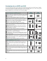
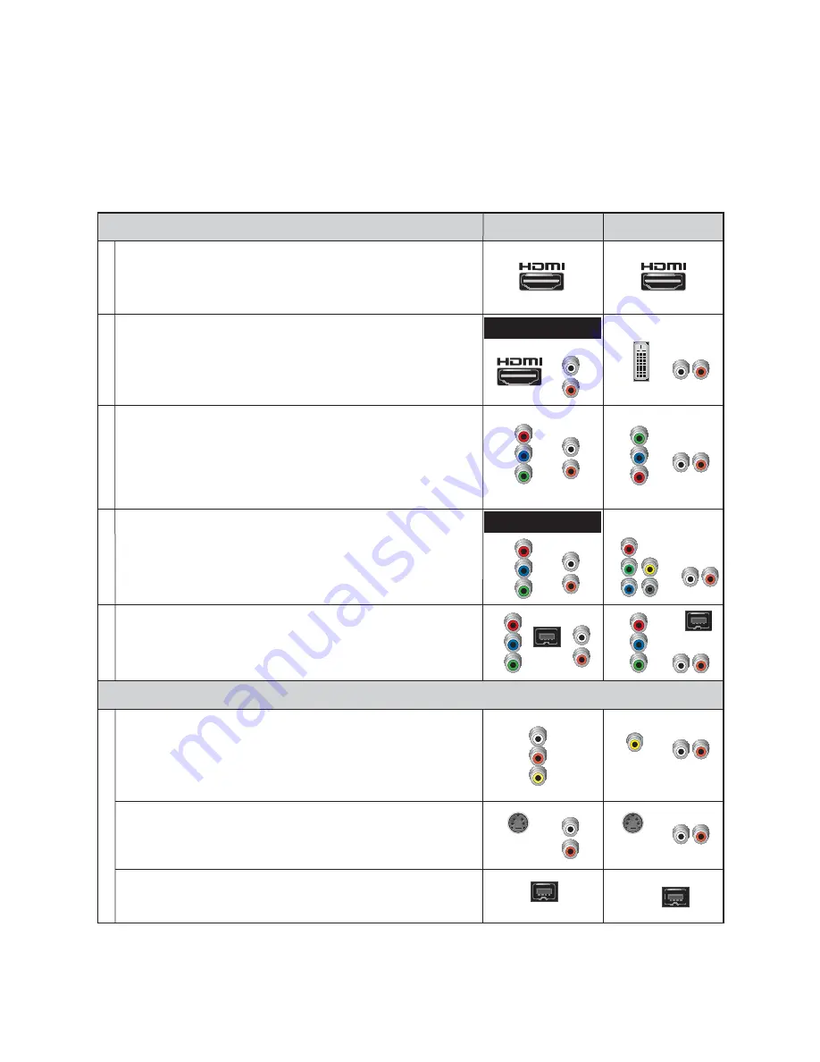
Connections for an HDTV and VCR 

To use the set-top with an HDTV, you must make 

one 

of the following connections to view the HD content. In addition, 

you can make connections to a digital or analog VCR to record to a VCR tape. Refer to your TV and VCR user guides 
and the cabling diagrams in this guide for more detailed connection information.

Note

: The labeling on your set-top, HDTV, and VCR may vary slightly.

1394

DVI

HDMI

YPbPr

RGB

Required Connections to an HDTV (use one)

Set-Top

Connections

HDTV

Connections

Some HDTVs have 1394 connectors. If you connect to your HDTV 
using 1394, you also need to connect separate video and audio 
connections to your HDTV.
See the connection diagram on page 16 for an example.

1394

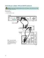
For VCRs with Video and Left and Right audio connectors, you 
can use the Out 2 connectors (Video, Left, and Right) on the 
set-top.
See the connection diagram on page 16 for an example.

VCR

For VCRs with S-Video and Left and Right audio connectors, you 
can use the S-Video Out and the Out 2 Left and Right connectors 
on the set-top.

Optional Connections to a VCR (use one)

Set-Top

Connections

VCR

Connections

Pr

Pb

Y

L

R

DVI

VIDEO

OUT 2

L

A

U

D

I

O

R

VIDEO

IN

L

R

AUDIO

IN

L

R

OUT 1

Y

Pr

Pb

L

R

OUT 1

L

R

Y

Pr

Pb

L

R

OUT 1

B

R

G

V

H

L

R

S-VIDEO

OUT

L

R

OUT 2

S-VIDEO

IN

L

R

Adapter Needed

Some HDTVs have a High-De

fi

 nition Multimedia Interface (HDMI) 

connector. The HDMI connector provides both a digital video and 
audio connection.
See the connection diagram on page 12 for an example.

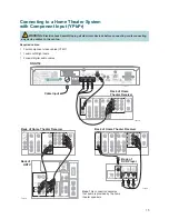
The YPbPr connectors can provide high-de

fi

 nition component 

video signals to an HDTV. 

Note

: Use the HD Setup Wizard on the set-top to set the HD 

mode and select the output video format that will matches the 
full capabilities of your HDTV. 
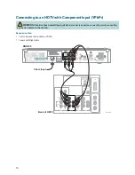
See the connection diagram on page 14 for an example.

The HDMI connector can provide the connection to an HDTV 
with a DVI input. If your HDTV has a Digital Visual Interface (DVI) 
connector, you will need an HDMI-to-DVI adapter, and you will 
need to connect a separate audio connection. 
See the connection diagram on page 13 for an example.

Some HDTVs have only RGB connectors. If you have one of 
these HDTVs, you need an RGB adapter. 
Check with your service provider for information about acquiring 
an RGB adapter, or you can purchase the adapter at your local 
electronics supplier.

Adapter Needed

Y

Pr

Pb

L

R

OUT 1

L

R

Y

Pr

Pb

1394

For 

Digital VCRs

, you can use the 1394 out connector on the 

set-top.

1394

1394

Summary of Contents for RNG150

Page 1: ...USB 2 0 RNG150 POWER DATA REMOTE User Guide Cisco RNG150 Digital Only High Definition Interactive Set Top with Multi Stream CableCARD Interface ...

Page 2: ...878 6 493 876 6 510 519 6 516 002 6 516 412 6 526 508 6 538 595 6 546 013 6 560 340 6 567 118 6 570 888 6 622 308 6 629 227 6 664 984 6 667 994 6 671 879 6 674 967 6 678 891 6 714 598 6 721 352 6 721 956 6 725 459 6 738 982 6 744 892 6 744 967 6 751 271 6 760 918 6 795 972 6 802 077 6 804 708 6 811 447 6 817 028 6 822 972 6 823 385 6 832 386 6 845 106 6 868 473 6 874 075 6 889 191 6 909 471 6 917 ...

Page 3: ... View Television Programming 8 Troubleshooting 9 Frequently Asked Questions 10 Picture Formats 11 Connecting to an HDTV with an HDMI Connector 12 Connecting to an HDTV with a DVI Connector 13 Connecting to an HDTV with Component Input YPbPr 14 Connecting to a Home Theater System with Component Input YPbPr 15 Connecting to a Stereo VCR and HDTV optional 16 Connecting to an HDTV with a 1394 Connecto...

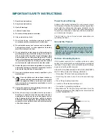
Page 4: ...rvicing is required when the apparatus has been damaged in any way such as a power supply cord or plug is damaged liquid has been spilled or objects have fallen into the apparatus the apparatus has been exposed to rain or moisture does not operate normally or has been dropped Power Source Warning A label on this product indicates the correct power source for this product Operate this product only ...

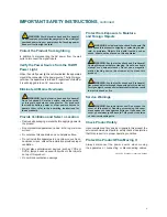
Page 5: ...rovides proper ventilation Do not place entertainment devices such as VCRs or DVDs lamps books vases with liquids or other objects on top of this product Do not block ventilation openings Protect from Exposure to Moisture and Foreign Objects WARNING Avoid electric shock and fire hazard Do not expose this product to dripping or splashing liquids rain or moisture Objects filled with liquids such as ...

Page 6: ...vi ...
Page 7: ...ws and information about this product For more information please refer to www scientificatlanta com products consumers new_cableboxes htm Safety First Before using the set top read the Important Safety Instructions section of this guide Identify Your Set Top To find the serial number for your set top look on the bottom for a label that is similar to the example shown here The serial number begins...

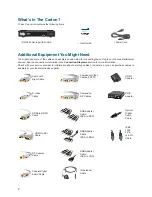
Page 8: ...les or adapters at your local electronics supplier Power Cord HDMI Adapter RGB Adapter Optical Digital Audio Cable IEEE 1394 4 Pin to 4 Pin Cable RNG150 Set top with M Card USB 2 0 RNG150 POWER DATA REMOTE RF Coaxial Cable Coaxial Digital Audio Cable S Video Cable Audio Left Right Cable HDMI to HDMI Cable HDMI to DVI Cable IR Extender Cable Composite A V Cables RGB Adapter Cable RCA to RCA Compone...

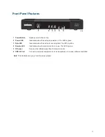
Page 9: ...is receiving data The LED is yellow 4 Remote LED Illuminates when the remote control is in use The LED is green 5 IR Sensor Receives the infrared signal from the remote control 6 USB 2 0 Port Connects to external equipment such as a keyboard or a mouse software controlled Note This illustration may vary from the actual product T13672 USB 2 0 RNG150 POWER DATA REMOTE 1 2 3 4 5 6 ...

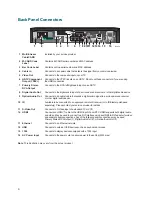
Page 10: ...eceiver or other digital audio device 10 IR Available to be connected to an approved remote IR receiver or to IR Blaster purchased separately Please contact your service provider for details 11 S Video Out Connects to S Video input of a standard TV or VCR 12 HDMI Connects an HDMI cable to the HDMI input of an HDTV HDMI supports both digital audio and video May be used to connect to a DVI interface...

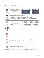
Page 11: ... set top and the TV into an AC power source that is not controlled by a switch 5 Do not turn on the set top or TV yet POWER 6 It may take several minutes for the set top to receive the latest software programming and service information Wait until you see one of the following displays on the front panel of the set top that indicates that the update is complete Current time Four dashes Note If four...

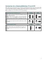
Page 12: ...ns Pr Pb Y L R DVI VIDEO OUT 2 L A U D I O R VIDEO IN L R AUDIO IN L R OUT 1 Y Pr Pb L R OUT 1 L R Y Pr Pb L R OUT 1 B R G V H L R S VIDEO OUT L R OUT 2 S VIDEO IN L R Adapter Needed Some HDTVs have a High Definition Multimedia Interface HDMI connector The HDMI connector provides both a digital video and audio connection See the connection diagram on page 12 for an example The YPbPr connectors can...

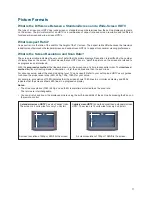
Page 13: ... connectors can provide standard definition component video signals to an SDTV Note To connect YPbPr to an SDTV you must set the HD Setup Wizard on the set top to HD Mode and select the output video format typically 480i that will match the capabilities of your SDTV The S Video Out connection provides an optimal video connection to SDTVs Y Pr Pb Pr Pb Y L R OUT 1 L R Set Top Connections SDTV Conne...

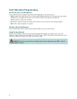
Page 14: ...ither from the on screen guide or while viewing a program Select View a specific program in the guide Stretch and Zoom Program You can stretch and zoom SD or HD programs by pressing the key on the remote control Avoid Screen Burn In Images such as letterbox bars or side bars bright closed captioning backgrounds station logos or any other stationary images may cause the picture tube in your HDTV to...

Page 15: ...hem to the set top Verify that the set top is set to the proper screen type and resolution No Color Verify that the current TV program is broadcast in color Adjust the TV color controls If you are using a component video connection YPbPr check that all connectors are completely plugged into the set top and TV No Sound If your setup includes a VCR or stereo verify that you have properly connected t...

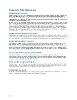
Page 16: ...ges on an SDTV set are crisp and clear noticeably better than on a standard analog television set using an antenna to receive over the air signals What is High Definition Television High definition television HDTV is a completely new way to send and receive television broadcast signals HDTV images are made up of pixels that are much smaller and closer together than those used in standard analog te...

Page 17: ...ssive method the lines are drawn on the screen one at a time in sequential order The interlaced method involves refreshing pixels in alternation first the odd lines and then the even lines For advance setup select the scan modes that your TV can support Refer to your set top and HDTV user s guides to choose the proper scan rates 480i 480p 720p 1080i for your setup For example a resolution of 1080i...

Page 18: ... AUDIO OUT connectors on the set top Notes If the TV is not Dolby Digital capable it may not produce audio through its speakers when the Audio Digital Out setting on the set top is set to Dolby Digital You can either switch the Audio Digital Out setting back to HDMI when you are not using the home theater or Dolby Digital decoder or you can connect the baseband audio outputs OUT 1 Audio Left and R...

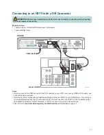
Page 19: ...CP to connect the set top to these devices Also refer to the Important Note Regarding the HDMI Interface on the Set top on page 12 RNG150 M CARD MAC 001BD746C7CB M CARD SN PKCPTMFDV HDMI AUDIO CENTER CHANNEL IN AUDIO IN DVI HDCP ANT 75 IN OUT L R ANT 1 HD 2 Y OUT ANT 2 PB PR L R VIDEO L MONO R L MONO R AUDIO IN ON OFF IN HD 1 S VIDEO VIDEO Y PB PR L R AUDIO AUDIO DVI HDCP IN AUDIO IN DVI HDCP L R ...

Page 20: ... L MONO R L MONO R AUDIO IN ON OFF IN HD 1 S VIDEO VIDEO Y PB PR L R AUDIO AUDIO Cable Input T13777 Back of HDTV Connecting to an HDTV with Component Input YPbPr WARNING Electric shock hazard Unplug all electronic devices before connecting or disconnecting any device cables to the set top Required cables 1 set component video cables YPbPr 1 audio Left Right cable ...

Page 21: ... PR Y PB PR L R AUDIO S VIDEO DIGITAL AUDIO TV CABLE 1 2 3 4 VIDEO L R AUDIO S VIDEO DVD VIDEO L R AUDIO S VIDEO VIDEO 1 S VIDEO OUT VIDEO OUT MONITOR VIDEO L R AUDIO S VIDEO OUT IN OUT IN T11135 RNG150 M CARD MAC 001BD746C7CB M CARD SN PKCPTMFDV Back of Home Theater Receiver COMPONENT VIDEO 1 Y PB PR 2 Y PB PR Y PB PR S VIDEO DIGITAL AUDIO TV CABLE 1 2 3 4 VIDEO L R AUDIO S VIDEO DVD VIDEO L R AU...

Page 22: ...ON OFF IN HD 1 S VIDEO VIDEO Y PB PR L R AUDIO AUDIO Cable Input Back of Stereo VCR Back of HDTV Note This connection allows for recording to the VCR and for watching VCR tapes on your HDTV To watch HD content use the HDMI YPbPr or DVI connector Connecting to a Stereo VCR and HDTV optional WARNING Electric shock hazard Unplug all electronic devices before connecting or disconnecting any device cab...

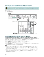
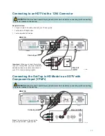
Page 23: ...NG Electric shock hazard Unplug all electronic devices before connecting or disconnecting any device cables to the set top Note The set top must be set to the proper output mode typically 480i Important When you connect the set top to your TV using 1394 you must make the additional video and audio connections to your TV to receive analog signals WARNING Electric shock hazard Unplug all electronic ...

Page 24: ...onnection 15 I Interlaced scan rate 11 IR Sensor 3 1394 4 6 17 A AC Outlet iv 4 Power input 4 Aspect ratio 11 B Back panel 4 Burn in of screen 8 C CableCard 2 4 10 Cables 2 Cable Out connector 4 Compliance FCC and Canadian EMI 21 Component video connection See YPbPr Composite 7 Connectors See also Front panel Back panel required for HDTV 6 required for SDTV 7 VCR 6 7 Connecting the set top to othe...

Page 25: ... 8 RGB connector See YPbPr S S Video 7 Safety ii iv v Scan rates 11 Screen burn in 8 resolution 11 size 11 SD mode 4 5 7 17 SDTV Connections 7 17 What is it 10 Serial number locating 1 Set top See Welcome Software updates 9 Sound troubleshooting 9 Standard definition What is it 10 Standard screen TV 11 Stretching and zooming picture 8 11 T Time display 5 Troubleshooting 9 TV digital what is it 10 ...

Page 26: ...9 USB port 3 V VCR connection 6 7 16 View programs 8 W Watch TV 1 8 Web access to product information 1 Welcome 1 Wide screen TV 11 Y YPbPr connector 4 6 7 HDTV connection 14 home theater connection 15 SDTV connection 17 Z Zoom picture 8 11 ...

Page 27: ...way Lawrenceville Georgia 30044 USA Telephone 770 236 1077 Canada EMI Regulation This Class B digital apparatus complies with Canadian ICES 003 Cet appareil numérique de la class B est conforme à la norme NMB 003 du Canada 20060628 FCC Standard Software and Firmware Use The software described in this document is protected by copyright law and furnished to you under a license agreement You may only...

Page 28: ...Inc Please see the Trademarks section of this document for a list of the Cisco Systems Inc trademarks used in this document All other trademarks mentioned in this document are the property of their respective owners Product and service availability is subject to change without notice 2008 by Cisco Systems Inc All rights reserved August 2008 Printed in United States of America 4026883 Rev A ...

Reviews: