3-26 Cisco 7010 Hardware Installation and Maintenance
Starting the Router
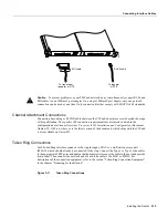
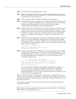
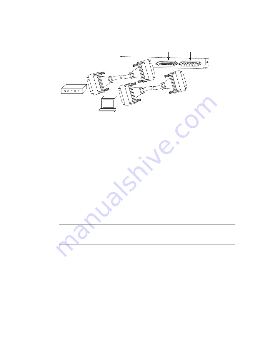
Figure 3-26
Console and Auxiliary Port Connections
Before connecting the console port, check your terminal’s documentation to determine the baud rate
of the terminal you will be using. The baud rate of the terminal must match the default baud rate
(9600 baud). Set up the terminal as follows:
•
9600 baud
•
8 data bits
•
No parity
•
2 stop bits
Use the console cable provided to connect the terminal to the console port on the RP (or RSP7000),
then follow the steps in the section “Starting the Router” later in this chapter.
Connecting Auxiliary Port Equipment
The auxiliary port is a DB-25 plug DTE port for connecting a modem or other DCE device (such as
a CSU/DSU or other router) to the router. The port is located on the RP (or RSP7000) above the
console port and is labeled Auxiliary. An example of a modem connection is shown in Figure 3-26.
Note
Both the console and auxiliary ports are asynchronous serial ports; any devices connected to
these ports must be capable of asynchronous transmission. (Asynchronous is the most common type
of serial device; for example, most modems are asynchronous devices.)
Starting the Router
When all interfaces are connected, perform a final check of all connections, then power up the router
as follows:
Step 1
Check the following components to make sure they are secure:
•
Each interface processor is inserted all the way into its slot, and all of the captive
installation screws are tightened.
•
All interface cable connections are secured.
•
The system power cord is connected and secured with the cable retention clip.
•
The Flash memory card, if present, is inserted all the way into its slot on the RP (or RSP7000).
Modem
Console terminal
Auxiliary
port
Console
port
H2037
Summary of Contents for TelePresence Server 7010
Page 10: ...x Cisco 7010 Hardware Installation and Maintenence ...
Page 14: ...iv Cisco 7010 Hardware Installation and Maintenance Document Conventions ...
Page 148: ...3 36 Cisco 7010 Hardware Installation and Maintenance Using the Flash Memory Card ...
Page 158: ...4 10 Cisco 7010 Hardware Installation and Maintenance Troubleshooting the Processor Subsystem ...
Page 242: ...5 84 Cisco 7010 Hardware Installation and Maintenance Replacing Internal Components ...
Page 258: ...A 16 Cisco 7010 Hardware Installation and Maintenance MIP Interface Cable Pinouts ...
Page 270: ...B 12 Cisco 7010 Hardware Installation and Maintenance Interface Processor LEDs ...
Page 274: ...C 4 Cisco 7000 Hardware Installation and Maintenance ...
Page 287: ...Index 13 ...


