Product Overview 1-35
Functional Overview
Port Densities
The three available interface slots support any combination of network interface processors, or any
three of the same type for the following maximum port densities:
•
Up to 3 ATM interfaces
•
Up to 18 Ethernet interfaces
•
Up to 22 Fast Ethernet ports (one or two interfaces per FEIP)
•
Up to 6 channel attachment interfaces
•
Up to 12 Token Ring interfaces
•
Up to 3 FDDI interfaces
•
Up to 24 serial interfaces
•
Up to 3 HSSI interfaces
•
Up to 6 multichannel ports for 180 serial interface
You can install any combination of interface processors in any of the three available interface
processor slots. There are no restrictions on either the number of interfaces possible or their location
with respect to the main system processor (RP).
Port Addresses
Each interface (port) in a Cisco 7000 series router uses several different types of addresses. The
physical port address is the actual physical location (slot/port) of the interface connector within the
chassis. The system software uses the physical addresses to control activity within the router and to
display status information. These physical slot/port addresses are not used by other devices in the
network; they are specific to the individual router and its internal components and software.
The system software also assigns a logical interface address to each interface, which is included in
some of the status displays. The logical address is used in our other modular platforms (A-type, M,
and C chassis) and is present in all router software, but it is not implemented (or needed) in the
Cisco 7000 series routers.
A third type of address is the MAC-layer or hardware address, which is a standardized data link layer
address that is required for every port or device that connects to a network. Other devices in the
network use these addresses to locate specific ports in the network and to create and update routing
tables and data structures. The Cisco 7000 series uses a unique method to assign and control the
MAC-layer addresses of its interfaces.
The following sections describe how Cisco 7000 series routers assign and control both the physical
(slot/port) and MAC-layer addresses for interfaces within the chassis.
Physical Interface Addresses
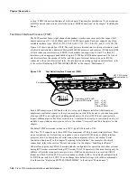
In the Cisco 7010, physical port addresses specify the actual physical location of each interface port
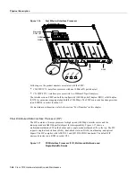
on the router interface processor end. (See Figure 1-24.) The address is composed of a two-part
number in the format slot/port number. The first number identifies the slot in which the interface
processor is installed (0 through 2, beginning at the bottom slot). The second number identifies the
physical port number on the interface processor. The ports on each interface processor are numbered
sequentially from left to right beginning with the port 0.
Summary of Contents for TelePresence Server 7010
Page 10: ...x Cisco 7010 Hardware Installation and Maintenence ...
Page 14: ...iv Cisco 7010 Hardware Installation and Maintenance Document Conventions ...
Page 148: ...3 36 Cisco 7010 Hardware Installation and Maintenance Using the Flash Memory Card ...
Page 158: ...4 10 Cisco 7010 Hardware Installation and Maintenance Troubleshooting the Processor Subsystem ...
Page 242: ...5 84 Cisco 7010 Hardware Installation and Maintenance Replacing Internal Components ...
Page 258: ...A 16 Cisco 7010 Hardware Installation and Maintenance MIP Interface Cable Pinouts ...
Page 270: ...B 12 Cisco 7010 Hardware Installation and Maintenance Interface Processor LEDs ...
Page 274: ...C 4 Cisco 7000 Hardware Installation and Maintenance ...
Page 287: ...Index 13 ...

