Preparing for Installation 2-35
Preparing Network Connections
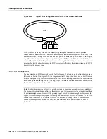
Figure 2-23
DAS Station Failure and Ring Recovery Example
A second failure could cause the ring to wrap in both directions from the point of failure, which
would segment the ring into two separate rings that could not communicate with each other. For
example, if Station 1 in Figure 2-23 fails after Station 3 fails, Stations 2 and 4 will each be isolated
because no path for communication exists between them. Subsequent failures cause additional
segmentation.
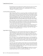
Optical bypass switches avoid segmentation by eliminating failed stations from the ring. During
normal operation, an optical bypass switch allows the light signal to pass directly through itself
uninterrupted. When a station with a bypass switch fails, the bypass switch reroutes the signal back
onto the ring before it reaches the failed station, so the ring does not have to wrap back on itself.
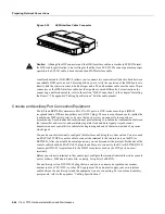
Figure 2-24 shows an optical bypass switch installed at Station 1. In the normal configuration shown
on the left, Station 1 is functioning normally, so the optical bypass switch appears transparent. The
switch essentially allows the signals to pass through it without interruption. However, if Station 1
fails, the optical bypass switch enables the bypassed configuration shown on the right in Figure 2-24.
The bypass switch reroutes the light signal by intercepting it before it reaches the failed Station 1
and sends it back out to the ring. This allows the signal to maintain its existing path and direction
without wrapping back on itself. However, stations that are operating normally repeat the signal
when sending it back out to the ring. Optical bypass switches do not repeat or drive the signal; they
just allow the signal to pass through them. Therefore, significant signal loss can occur when the
downstream neighbor, the next station on the ring, is far away.
Station 4
Station 3
Station 2
Station 1
Ring wrap
Ring wrap
B
A
MAC
B
A
MAC
B
A
B
A
MAC
Failed station
H1589a
Summary of Contents for TelePresence Server 7010
Page 10: ...x Cisco 7010 Hardware Installation and Maintenence ...
Page 14: ...iv Cisco 7010 Hardware Installation and Maintenance Document Conventions ...
Page 148: ...3 36 Cisco 7010 Hardware Installation and Maintenance Using the Flash Memory Card ...
Page 158: ...4 10 Cisco 7010 Hardware Installation and Maintenance Troubleshooting the Processor Subsystem ...
Page 242: ...5 84 Cisco 7010 Hardware Installation and Maintenance Replacing Internal Components ...
Page 258: ...A 16 Cisco 7010 Hardware Installation and Maintenance MIP Interface Cable Pinouts ...
Page 270: ...B 12 Cisco 7010 Hardware Installation and Maintenance Interface Processor LEDs ...
Page 274: ...C 4 Cisco 7000 Hardware Installation and Maintenance ...
Page 287: ...Index 13 ...

