1-32 Cisco 7010 Hardware Installation and Maintenance
Physical Description
Table 1-6
Model Numbers and Descriptions of E1-G.703/G.704 Port Adapter and Cables
HSSI Interface Processor (HIP)
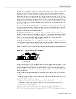
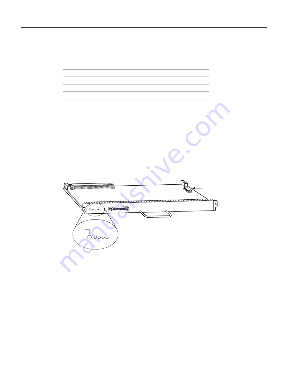
The HIP, shown in Figure 1-21, provides a full-duplex synchronous serial interface for transmitting
and receiving data at rates of up to 52 Mbps. The HSSI interface, recently standardized as
EIA/TIA-612/613, provides access to services at T3 (45 Mbps), E3 (34 Mbps), and SONET STS-1
(51.82 Mbps) rates. The actual rate of the interface depends on the external data service unit (DSU)
and the type of service to which it is connected. The default HIP microcode resides on an ROM in
socket U133.
Figure 1-21
High-Speed Serial (HSSI) Interface Processor (HIP)
As with the other interface processors, the enabled LED is on when the HIP is enabled for operation.
The four LEDs above the HSSI port (see Figure 1-21) indicate the following:
•
RT (Receive Timing)—When on, indicates that the HIP has detected a receive clock signal.
During normal operation, this signal is received from the external DSU. During loopback, this
signal is generated internally.
•
RD (Receive Data)—On when the HIP detects packet traffic and indicates that the HIP is able to
receive packets from the external DSU.
•
ST (Send Timing)—On when the HIP is sending a transmit clock signal to the external DSU.
During normal operation, this signal is derived from the receive timing (RT) signal from the
external DSU. During loopback, this signal is generated internally.
•
C (Connected)—When on, indicates normal operation; the HIP is properly connected to the
external DSU, and TA (DTE available) and CA (DCE available) are active. This LED is off when
the HIP is in loopback mode and when it is not connected to the DSU.
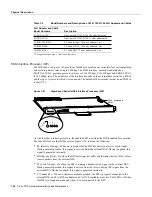
Port Adapter and Cable
Model Numbers
Description
PA-7KF-E1/120=
1
1. The appended equal sign (=) indicates a spare part.
Dual-port E1-G.703/G.704 120 ohm, balanced
PA-7KF-E1/75=
Dual-port E1-G.703/G.704 75 ohm, unbalanced
CAB-E1-TWINAX=
E1 cable twinax 120 ohm, balanced, 5 m
CAB-E1-DB15=
E1 cable, DB-15, 120 ohm, balanced, 5 m
CAB-E1-BNC=
E1 cable BNC 75 ohm, unbalanced, 5 m
H2008
U133, microcode
ROM
Enabled
RT
RD
ST
C
Summary of Contents for TelePresence Server 7010
Page 10: ...x Cisco 7010 Hardware Installation and Maintenence ...
Page 14: ...iv Cisco 7010 Hardware Installation and Maintenance Document Conventions ...
Page 148: ...3 36 Cisco 7010 Hardware Installation and Maintenance Using the Flash Memory Card ...
Page 158: ...4 10 Cisco 7010 Hardware Installation and Maintenance Troubleshooting the Processor Subsystem ...
Page 242: ...5 84 Cisco 7010 Hardware Installation and Maintenance Replacing Internal Components ...
Page 258: ...A 16 Cisco 7010 Hardware Installation and Maintenance MIP Interface Cable Pinouts ...
Page 270: ...B 12 Cisco 7010 Hardware Installation and Maintenance Interface Processor LEDs ...
Page 274: ...C 4 Cisco 7000 Hardware Installation and Maintenance ...
Page 287: ...Index 13 ...


