Cisco UCS C24 M3 High-Density SFF Rack-Mount Server
42
SUPPLEMENTAL MATERIAL
CPUs and DIMMs
Physical Layout
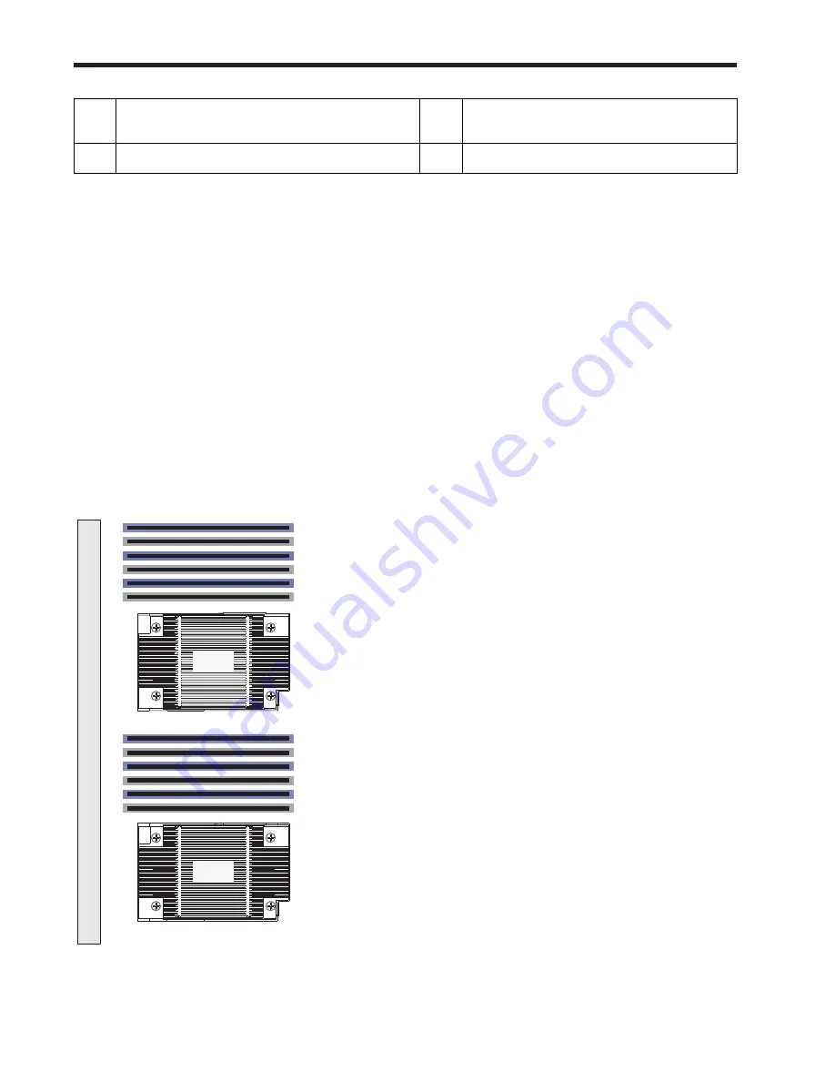
Each CPU has three DIMM channels:
■
CPU1 has channels A, B, and C
■
CPU2 has channels D, E, and F
Each DIMM channel has two banks: Bank 0 and Bank 1. The blue-colored DIMM banks are for Bank 0 and the
black-colored are for Bank 1.
As an example, DIMM slots A0, B0, and C0 belong to Bank 0, while A1, B1, and C1 belong to Bank 1.
shows how banks and channels are physically laid out on the motherboard. The DIMM slots on the
top (channels A, B, and C) are associated with CPU 1, while the DIMM slots on the bottom (channels D, E,
and F) are associated with CPU 2. Bank 0 slots (blue) are populated before Bank 1 slots (black).
Figure 7
Physical Layout of CPU DIMM Channels and Banks
6
CPUs and heatsinks (up to two)
13
RAID backup unit mounting locations
(two)
7
PCIe riser 1 (two full-height slots)
-
-
285209
A0
A1
B0
B1
C0
C1
D0
D1
E0
E1
F0
F1
Front of Server
CPU1
CPU2


