


3-10
Cisco UCS C420 Server Installation and Service Guide
OL-27640-01
Chapter 3 Maintaining the Server
Preparing for Server Component Installation
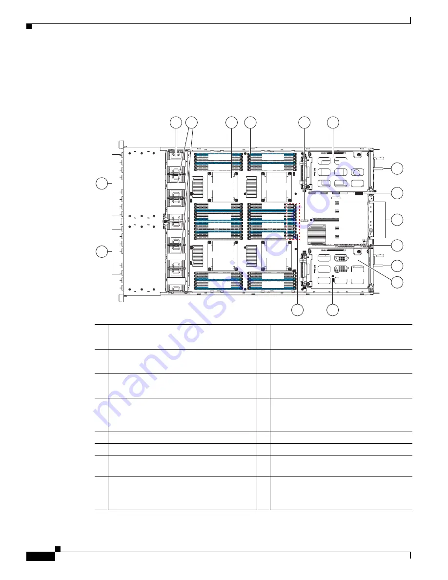
Replaceable Component Locations
This section shows the locations of the components that are discussed in this chapter. The view in
Figure 3-5
is from the top down with the top cover removed.
Figure 3-5
Replaceable Component Locations
1
Drive bay module 2
(up to eight 2.5-inch drives, hot-pluggable)
9
Power supply 2 (hot-pluggable)
2
Drive bay module 1
(up to eight 2.5-inch drives, hot-pluggable)
10
USB 2.0 slot on motherboard
3
Fan tray, with six hot-pluggable fan modules
11
PCIe slots 2–6 on motherboard
See also
Figure 3-23 on page 3-43
for details.
4
Drive backplane transition cards
(up to two on chassis floor, not visible under
fan tray in this view)
12
I/O riser (includes two sockets for Cisco
FlexFlash cards)
5
CPUs and heatsinks (two or four)
13
Power supply 1 (hot-pluggable)
6
DIMM sockets on motherboard (up to 48)
14
PCIe riser 2 (horizontal PCIe slot 1)
7
RTC battery on motherboard
15
TPM socket (on motherboard, not visible
under power supply in this view)
8
PCIe riser 1 (horizontal PCIe slot 7)
16
RAID backup unit (supercap power module)
mounting location
(two, on air baffle not shown in this view)
FAN 1
FAN 2
FAN 3
FAN 4
FAN 5
FAN 6
DIMM L
DIMM M
DIMM G
DIMM H
DIMM K
DIMM J
DIMM F
DIMM E
DIMM R
DIMM C
DIMM S
DIMM D
PCle 7
PCle 6
PCle 5
PCle 4
PCle 3
PCle 2
PCle 1
DIMM P
DIMM B
DIMM N
DIMM A
CPU 3
CPU 2
CPU 4
CPU 1
15
9
10
12
13
14
11
3
6
7
8
5
4
2
1
16
334353


