Contents
Page 142
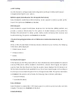
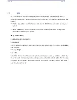
ACPI Settings
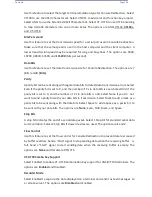
Use this feature to configure Advanced Configuration and Power Interface (ACPI) power
management settings for your system.
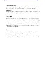
NUMA Support (Available when the OS supports this feature)
Select Enabled to enable Non-Uniform Memory Access support to enhance system perfor-
mance. The options are
Enabled
and Disabled.
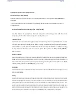
WHEA Support
Select Enabled to support the Windows Hardware Error Architecture (WHEA) platform and
provide a common infrastructure for the system to handle hardware errors within the
Windows OS environment to reduce system crashes and to enhance system recovery and
health monitoring. The options are
Enabled
and Disabled.
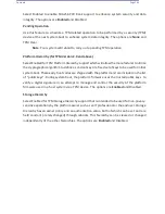
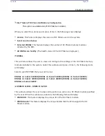
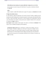
Trusted Computing (Available when a TPM device is installed and detected by the
BIOS)
When a TPM (Trusted-Platform Module) device is detected in your machine, the following
information will be displayed.
•
TPM2.0 Device Found
•
Firmware Version
•
Vendor
Security Device Support
If this feature and the TPM jumper (JPT1) on the motherboard are both enabled, the onboard
security (TPM) device will be enabled in the BIOS to enhance data integrity and system
security. Note that the OS will not show the security device. Neither TCG EFI protocol nor
INT1A interaction will be made available for use. If you have made changes on the setting on
this item, be sure to reboot the system for the changes to take effect. The options are Disable
and
Enable
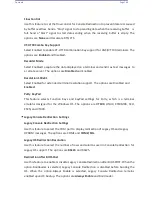
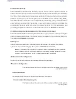
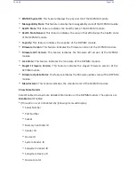
. If this option is set to Enable, the following screen and items will display:
•
Active PCR Banks
•
Available PCR Banks
SHA-1 PCR Bank
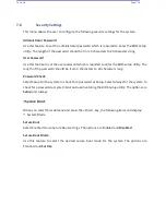
Select Enabled to enable SHA-1 PCR Bank support to enhance system security and data
integrity. The options are
Enabled
and Disabled.
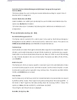
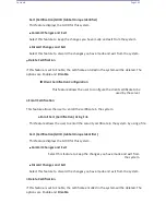
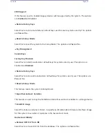
SHA256 PCR Bank
Summary of Contents for UCS C890 M5
Page 15: ...Contents Page 15 Location of the C890 M5 BMC Card ...
Page 19: ...Contents Page 19 Five 5 C890 M5 PCIEBOARD on the Rear side of Midplane ...
Page 25: ...Contents Page 25 C890 M5 BPLANE Midplane Layout Rear Side ...
Page 26: ...Contents Page 26 Front View of the C890 M5 BPLANE Midplane ...
Page 27: ...Contents Page 27 Rear View of the C890 M5 BPLANE Midplane ...
Page 28: ...Contents Page 29 2 3 14 Location of the C890 M5 BPLANE Midplane The CPU Board ...
Page 44: ...Contents Page 46 ...
Page 48: ...Contents Page 50 Mixed DIMM DC PMem Population Table ...
Page 55: ...Contents Page 57 6 Pull the card out of the PCI E board Removing a PCI E Module 3 4 ...
Page 56: ...Contents Page 58 Removing a PCI E Card from a PCIE Module 5 6 ...
Page 59: ...Contents Page 61 Installing a PCI E Card in a CPU Module ...
Page 60: ...Contents Page 62 Installing a PCI E Card in a CPU Module cont ...
Page 62: ...Contents Page 64 Installing a PCI E Card in a Storage Module ...
Page 64: ...Contents Page 66 Installing the Battery 3 2 ...
Page 66: ...Contents Page 68 Mounting a Drive in a Carrier ...
Page 70: ...Contents Page 72 Removing the Storage Module Cover ...
Page 71: ...Contents Page 73 Installing Removing 2 5 HDDs with bracket ...
Page 86: ...90 Contents Page 90 ...
Page 90: ...95 Contents Page 95 ...
Page 163: ...Contents Page 168 Save changes and Reset ...
Page 165: ...Contents Page 170 ...
Page 167: ...Contents Page 172 ...
Page 168: ...Contents Page 173 ...
Page 169: ...Contents Page 174 Emulex FC ...
Page 171: ...Contents Page 176 ...
Page 178: ...BIOS PCIe Configuration Page 183 Save changes and Reset ...
Page 179: ...BIOS PCIe Configuration Page 184 Confirm by selecting yes ...
Page 182: ...BIOS PCIe Configuration Page 187 ...
Page 183: ...BIOS PCIe Configuration Page 188 ...
Page 184: ...BIOS PCIe Configuration Page 189 ...
Page 185: ...BIOS PCIe Configuration Page 190 ...
Page 186: ...BIOS PCIe Configuration Page 191 ...
Page 188: ...BIOS PCIe Configuration Page 193 Default is enabled ...
Page 190: ...BIOS PCIe Configuration Page 195 ...
Page 191: ...BIOS PCIe Configuration Page 196 ...

