Contents
Page 55
4.3.6.5
PCI-E Expansion Card Installation
The Cisco UCS C890 M5 Rack Server supports up to 23 PCI-E 3.0 slots: five are in the
rear five PCI-E modules,
sixteen are in the eight front CPU modules, two are inside
the storage module.
4.3.6.6
The Rear Five PCI-E Modules
Each module can support one FHHL PCI-E 3.0 x16 card, which features a hot-plug*
capability for adding and removing PCI-E cards.
4.3.6.7
The Front Eight CPU Modules
Each CPU module has two PCI-E bays, and together to support the one of the
following
configurations:
Up to sixteen full-height (FH) PCI-E 3.0 x16 cards
Up to eight GPUs plus 16 U.2 NVMe drives or eight full-height (FH) PCI-E
3.0 x16 cards
Up to thirty-two U.2 NVMe drives
4.3.6.8
Inside the Storage Module
The storage module supports two low-profile (LP) PCI-E 3.0 x8 (in x16 slot) internal
cards,
or one full-height (FH) PCI-E 3.0 x8 (in x16 slot) internal cards via riser for OEM.
4.3.6.9
PCIE Module
Perform the following steps to replace a PCI-E card in one of five hot-plug PCI-E
modules at the rear of the system while the system is on.
Note
: Both the OS and PCI-E card must support the hot-plug feature.
4.3.6.10
Removing a Hot-Plug PCI-E Card
1.
Initiate a hot-removal request by pushing the Attention Button on the
corresponding slot. The green power LED will blink to indicate the module is in
a transition state. (To cancel the hot-plug removal operation, press the
Attention Button again within five seconds.)
2.
The power LED will turn off, showing that it is safe to remove the module. If
not, it indicates the request has failed (possibly due to client's software
unwilling to relinquish the device).
Summary of Contents for UCS C890 M5
Page 15: ...Contents Page 15 Location of the C890 M5 BMC Card ...
Page 19: ...Contents Page 19 Five 5 C890 M5 PCIEBOARD on the Rear side of Midplane ...
Page 25: ...Contents Page 25 C890 M5 BPLANE Midplane Layout Rear Side ...
Page 26: ...Contents Page 26 Front View of the C890 M5 BPLANE Midplane ...
Page 27: ...Contents Page 27 Rear View of the C890 M5 BPLANE Midplane ...
Page 28: ...Contents Page 29 2 3 14 Location of the C890 M5 BPLANE Midplane The CPU Board ...
Page 44: ...Contents Page 46 ...
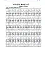
Page 48: ...Contents Page 50 Mixed DIMM DC PMem Population Table ...
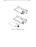
Page 55: ...Contents Page 57 6 Pull the card out of the PCI E board Removing a PCI E Module 3 4 ...
Page 56: ...Contents Page 58 Removing a PCI E Card from a PCIE Module 5 6 ...
Page 59: ...Contents Page 61 Installing a PCI E Card in a CPU Module ...
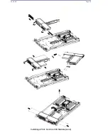
Page 60: ...Contents Page 62 Installing a PCI E Card in a CPU Module cont ...
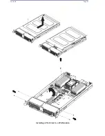
Page 62: ...Contents Page 64 Installing a PCI E Card in a Storage Module ...
Page 64: ...Contents Page 66 Installing the Battery 3 2 ...
Page 66: ...Contents Page 68 Mounting a Drive in a Carrier ...
Page 70: ...Contents Page 72 Removing the Storage Module Cover ...
Page 71: ...Contents Page 73 Installing Removing 2 5 HDDs with bracket ...
Page 86: ...90 Contents Page 90 ...
Page 90: ...95 Contents Page 95 ...
Page 163: ...Contents Page 168 Save changes and Reset ...
Page 165: ...Contents Page 170 ...
Page 167: ...Contents Page 172 ...
Page 168: ...Contents Page 173 ...
Page 169: ...Contents Page 174 Emulex FC ...
Page 171: ...Contents Page 176 ...
Page 178: ...BIOS PCIe Configuration Page 183 Save changes and Reset ...
Page 179: ...BIOS PCIe Configuration Page 184 Confirm by selecting yes ...
Page 182: ...BIOS PCIe Configuration Page 187 ...
Page 183: ...BIOS PCIe Configuration Page 188 ...
Page 184: ...BIOS PCIe Configuration Page 189 ...
Page 185: ...BIOS PCIe Configuration Page 190 ...
Page 186: ...BIOS PCIe Configuration Page 191 ...
Page 188: ...BIOS PCIe Configuration Page 193 Default is enabled ...
Page 190: ...BIOS PCIe Configuration Page 195 ...
Page 191: ...BIOS PCIe Configuration Page 196 ...

